GALILEO
GALILEI" (GG)
A Small Satellite to Test the
Equivalence Principle of Galileo, Newton and Einstein
Proposal to ESA, F2&F3 Competition, January 31 2000
5. Status of the GGG (GG on the Ground) Prototype Experiment
The GG test of the Equivalence Principle is designed for space for two reasons: a driving signal stronger than on Earth (by about 3 orders of magnitude) and the absence of weight (the largest perturbation is @ 108 times smaller than 1-g). Yet, a 1-g version of GG can be conceived. This is possible because in the GG design the expected signal lies in the plane perpendicular to the spin/symmetry axis of the test cylinders (Figure 2.1): if on the ground the apparatus is suspended against local gravity along this axis, an EP violation signal has a component in the horizontal plane that the system is sensitive to. If the mechanical suspensions are stiff along the vertical (enough to withstand weight) and soft in the horizontal plane (in order to provide a very weak mechanical coupling of the test cylinders26, Ch. 3), the rotor is safe and at the same time it is very sensitive to differential forces in the horizontal plane, such as the force due to a possible violation of Equivalence.
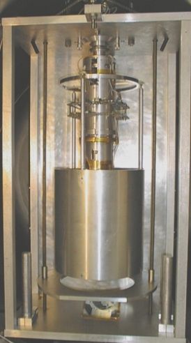
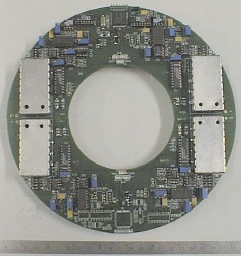
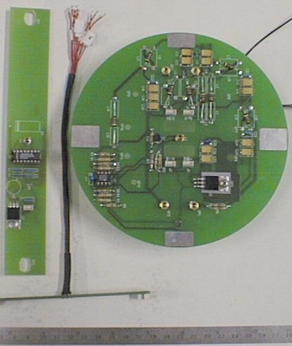
The GGG apparatus, located at the Laben laboratories in Florence, is shown in Figure 5.1. It is mounted on a metal frame fixed inside a vacuum chamber of 1m diameter. The test cylinders, of which only the outer one is visible in the picture, weigh 10kg each (as in GG) and so far are both made of Al. The capacitance plates of the read out, which measure the relative displacements of the test cylinders in the horizontal plane, are located in between the test cylinders. The suspension tube, held by a shaft turning inside ball bearings is shown. Inside this tube is the most delicate mechanical part of the apparatus: the coupling arm, and 3 laminar cardanic suspensions26, Ch. 3, one for carrying the total weight (at the center of the arm), one for suspending the outer test cylinder (at the top of the arm), and one for suspending the inner test cylinder (at the bottom of the arm). Such a mechanical system is very similar to an ordinary beam balance (with a vertical beam), so that masses and lengths can be adjusted to make it most sensitive to differential effects (balancing to Dm/m=1/200,000 achieved). The electronic core of the experiment is shown in Figure 5.2; the annular shape of the support is for placing the circuits around the suspension tube and for reasons of cylindrical symmetry. The digitized signal produced by these circuits (giving the relative displacements of the test cylinders as an electric signal) is optically transmitted to the non rotating system, and eventually outside the vacuum chamber to the computer. The required electronics (located at the top of the metal frame shown in Figure 5.1), is shown in Figure 5.3. Sliding contacts are used for power transmission inside the rotor. Details of the GGG design and its parts - particularly the laminar cardanic suspensions which are an essential component of the system- are given in26, Ch. 3.
An EP violation with the Earth as the source mass would cause a constant displacement of the GGG test rotors in the North-South direction. However, due to the diurnal rotation of the Earth, a gyroscopic effect arises between the test rotors (proportional to the spin rate of the apparatus) which is also in the North-South direction and much larger: in the current design it amounts to about 3m m38. A non zero tilt angle between the spin axis and the direction of local gravity would also give rise to a constant relative displacement (in the direction of the residual tilt). The GGG apparatus must therefore look for a possible EP violation signal with the Sun as the source mass, like in the experiments by8,9. This means a driving signal 1400 times weaker than it is in space for GG. Note that none of these difficulties (verticality of the rotation axis and gyroscopic effect) would affect the GG space experiment, in which there is no local gravity preferential direction and no gyroscopic effect (the rotation axis is almost perfectly fixed in space, and moreover - unlike in GGG- the test cylinders are suspended by their centers of mass26, Ch. 2.1.2 and Ch. 3).
The sensitivity of the GGG capacitance read-out has been tested on bench in 1998, finding that it can measure 5 picometer displacements in 1 sec integration time. This is fully adequate for the GG space experiment, which must be sensitive to slightly less than 1 picometer displacements in order to fulfill its goal of an EP test to 10-17; less than 100 sec integration time is enough for the GGG read out to complete the task. This result is to be expected for a carefully designed capacitance bridge. However, things are more difficult when the read out is mounted on the real apparatus for a real measurement. The best result obtained with the GGG apparatus operational on the 4th floor of the Laben building is shown in Figure 5.4. The rotor has been running at 6Hz for more than 1hr, and the two data sets reported are separated in time by 1/2 hour. It appears that, on the average over all spin periods, the test cylinders are displaced in an almost fixed direction of the horizontal plane by about 6.5mm. This is due to a residual tilt of the rotation axis with respect to the direction of local gravity which adds up to the expected gyroscopic effect at this spin rate (@ 3.6mm). More important, this displacement is almost constant, within 0.2mm. This is the best sensitivity that could be achieved while GGG was located on the 4th floor of the Laben building, in spite of the fact that the capacitance read out in itself was much more sensitive. The physical limitation was seismic noise at low frequencies. For this reason, on January 2000, the entire apparatus (GGG, the vacuum chamber and all instruments) was moved to a less noisy location, in the basement of the Laben building, almost fully underground, where years ago was installed and operational a particle accelerator.
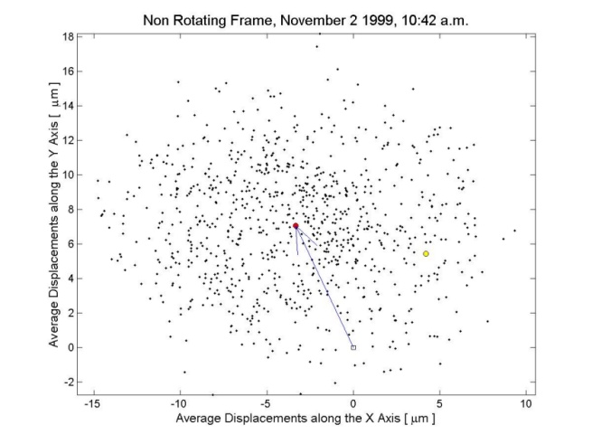

Figure 5.4
Relative displacements of the GGG test cylinders in the horizontal plane as recorded at about 1/2 hr distance without stopping the rotor or acting on the system in any way. The spin rate is 6 Hz, the oil damper is on (whirl motions are well damped; the natural period of differential oscillations is 12 sec), each dot is the relative position of the test cylinders averaged over one spin period (as recorded by the reference signal). The yellow dot is the average position for the first spin period of the data set. The red dot is the average of all black dots; the vector drawn gives the average relative position vector of the test cylinders over the entire data set. It is apparent that the two vectors are very close to one another; indeed, the data show that in half an hour the GGG test rotors maintain a constant relative displacement (in a given direction of the horizontal plane) of about 6.5mm to within 0.2mm. Therefore, this test proves a sensitivity of the GGG apparatus to relative displacements of the test bodies of 0.2mm.In order to measure low frequency seismic noise independently, an ISA (Italian Spring Accelerometer) instrument was installed next to GGG on January 14, 2000 thanks to V. Iafolla and colleagues. Figure 5.5 shows a 1-day measurement data by ISA. ISA does not distinguish horizontal forces in one direction from torques around the other direction in the plane, i.e. horizontal effects from tilts. In GGG horizontal oscillations of the terrain (hence of the vacuum chamber) are rejected extremely well (by a factor 108; see26, Ch. 3) leaving negligible differential perturbations. Instead, tilts of the terrain are, in the current set-up, only slightly rejected (by a factor 5 only). To be conservative we assume that all effects measured by ISA are due to tilts; from these data we compute the resulting relative displacement of the GGG test cylinders, and this gives an upper limit for what has to be expected from seismic noise at low frequencies. These data give, for the current GGG set up, a diurnal oscillation (upper limit) of @ 0.5mm; over 1/2 hr the effect is about 2 orders of magnitude smaller than the one measured on the 4th floor, amounting to a few 10-3
mm.
Figure 5.5 A 24-hr data set taken by the ISA accelerometer next to the GGG apparatus in the basement of the Laben building (Florence). ISA data are plotted as tilt angles, in the assumption that all the effect measured by the instrument is due to tilts and that there are no horizontal oscillations. Since GGG is almost insensitive to horizontal oscillations of the terrain, these data allow us to compute an upper limit for the relative displacements to be expected between the GGG test cylinders due to seismic noise at low frequencies.
In summary, while the read out in itself is fully adequate for the GG mission to meet its goal, the GGG prototype data as of November 1999 were 5 orders of magnitude away from the sensitivity to relative displacements of the test cylinders required in the GG space experiment. In the current underground location, a reduced level of seismic noise allows this gap to be reduced by about 2 orders of magnitude. Further reduction requires low frequency seismic tilts to be attenuated on GGG; a laminar, cardanic suspension similar in its geometry to the three in use for the test cylinders26, Ch. 3 has been designed for suspending the whole GGG apparatus from the vacuum chamber. Calculation of the transfer function shows that a reduction factor by 1/200,000 can be achieved, and that no spurious mode is introduced close to those of the GGG dynamical system. Then, differential displacements due to lunisolar tides will become relevant (@ 10-3
mm), all with well known frequencies and phases. Only the 24-hr tesseral harmonic due to the Sun competes with the GGG expected signal. However, it has a distinct signature in response to the declination of the Sun (zero at the equinoxes; maximum at the solstices) to be filtered out from a 3-month measurement series (data taking does not need to be continuous). For an EP test of its own GGG has, w.r.t GG, a weaker signal and a stiffer coupling of the test bodies (inevitable at 1-g). Yet, we are confident that it can compete with the best torsion balance ground tests.The importance of a full scale ground test is apparent. All crucial items of the space experiment (except drag free control) are tested in the lab, where local gravity is obviously a disadvantage; should any major difficulty arise - which might have been overlooked in the theoretical analysis and the numerical simulations of the space experiment- it can be fixed; were the problem to be a fundamental obstacle, the funding Agencies would have the choice to stop the project before construction begins.