3 The GG payload prototype on the Ground (GGG)
3.1 The Goals
3.2 Similarities and Differences with the GG Space experiment
3.3 The Conceptual Design
3.4 The Apparatus
3.5 State and Perspectives
3.1 The Goals
"Galileo Galilei on the Ground" (GGG) is an experiment to test the Equivalence Principle with an apparatus very similar to a prototype of the payload designed for the GG space experiment. The experiment is carried out in the laboratories of Laben in Florence; it has been designed by the GG scientists at the University of Pisa and is under the responsibility of Dr D. Bramanti. The scientific goal is to test the Equivalence Principle to 1 part in 1013, which would improve the accuracy of current laboratory tests by an order of magnitude. Since the apparatus used is a prototype of the space payload, GGG can validate the proposed space mission and be a valuable experiment in its own right. In turn, the design of the space experiment does substantially benefit from experience gained in the laboratory, as it has already happened.
3.2 Similarities and Differences with the GG Space experiment
If two test bodies of different composition orbit around the Earth at an altitude
h the EP violation signal at level h of the Eötvös adimensional parameter driven by the Earth as a source mass is given by Eq. (1.2). For h=520 km, it amounts to: aEP @ 8.4× h m/sec2 . The experiment is made by comparing the equilibrium positions of the bodies under the gravitational attraction from the Earth (proportional to the gravitational mass of the body), and the centrifugal force due to their orbital motion around the Earth (proportional to the inertial mass of the body). If the test bodies are coaxial cylinders the displacement vector resulting from an EP violation is always directed to the center of the Earth (see Fig. 1.1). Instead, if the bodies are suspended on the ground each of them reaches equilibrium when the component on the horizontal plane of the centrifugal force due to the diurnal rotation of the Earth is balanced by the horizontal component of the local gravitational attraction. This is the equilibrium position of an ordinary plumb line, which does not point to the center of the Earth because of the centrifugal force due to the rotation of the Earth, but it is displaced always along the North-South direction. Therefore, the EP violation signal (with the Earth as the source mass) is:![]() (3.1)
(3.1)
where S is the latitude of the laboratory and g ã is the diurnal angular velocity of the Earth; the maximum value of (3.1) is at
45° latitude ad amounts to 1.69× 10⁻² m/sec2 , about 500 times smaller than in space. Being the displacement fixed in the North-South direction there is no modulation of the effect. If instead one takes the Sun as the driving source mass, the equilibrium of the suspended body is between the gravitational attraction from the Sun and the centrifugal force due to the annual rotation around it. The resulting signal is, at most:![]() (3.2)
(3.2)
(
D is the Earth-Sun distance and Msun the mass of the Sun); its intensity is modulated by the diurnal rotation of the Earth from a minimum value depending on the latitude (as sinS ) and the maximum given by (3.2). If the ground experiment is carried out with the Earth as a source, the signal in space given by Eq. (1.2) is 500 times stronger; if the ground experiment uses the Sun as a source in order to provide a diurnal modulation, then the signal in space (still with the Earth as a source) is at least 1400 times stronger. Note that a space experiment with the Sun as a source has no advantage over the ground ones.In the GGG experiment the EP violation signal, constant in time and fixed in direction in the horizontal plane, is modulated at the spinning frequency with the spin axis in the vertical direction, similarly to GG. The spin frequency can be higher than
2 Hz (10 Hz reached so far) but the mechanical coupling of the test bodies cannot be as weak as in space; the apparatus is somewhat different because of local gravity but, it is based on the same dynamical principle (see Sec. 3.3)Whirl motions can be damped both passively and actively, and active damping can be both rotating and non rotating (GG needs active rotating damping, as discussed in Sec. 2.1.5 and in Chap. 6). GGG needs no drag compensation because there is no drag; instead, there is seismic noise which - similarly to air drag- is in principle common mode. It is partially rejected by balancing the test bodies and partially attenuated. The read-out capacitance system is in all similar to the GG read-out and it can reach, in terms of displacement measurements, the same sensitivity as it is required for GG.
In GG the whole spacecraft spins with the test masses, which makes perturbations from all local mass anomalies DC (see Sec. 2.2.5); this is not the case on the ground. The effect is less severe than in torsion balances because the test cylinders are very well centered on one another. In any case it can be taken care of, similarly to how it is done in torsion balance experiments (Sue et al., 1994), i. e. by using test masses specially designed to amplify the perturbations from local anomalies and then compensate for them with appropriate nearby masses. Effects on the spin axes of the test cylinders are also different in GGG as compared to GG because the GGG test bodies are not suspended from their center mass. The gravitational torque caused by the local acceleration of gravity, and the torque due to the fact that the laboratory is rotating with the Earth (hence it is not an inertial system), affect the equilibrium position of the coupled test bodies. These effects have been the subject of theoretical analysis and numerical simulation, and are to be compared with the experimental results (Comandi, 1998). In GG the test cylinders are suspended from their centers of mass and the spin axis is subject only to a slow precession (see Sec. 2.1.2).
The GGG experiment set up is made of two test bodies (in the shape of coaxial cylinders) in a coupled mechanical suspension (as shown in Fig. 3.1). In between the test cylinders are placed capacitance sensors forming a bridge to measure displacements of the test cylinders relative to one another in the horizontal plane. A motor sets the whole system in rotation along a vertical axis. The laminar suspensions shown in Fig. 3.3 are designed to withstand the local force of gravity along the vertical while being very weak in response to any force in the horizontal plane.
In more detail, with reference to Fig 3.1, the system can be described as follows. It is made of 4 rotors. One is the suspension tube, held by a shaft turning inside ball bearings; rotation is transmitted from the motor (in violet on the left) to the central shaft by means of 2 O-rings (not shown in this Figure) on pulleys. The 2 test cylinders are shown in green (the inner one) and blue (the outer one). They are suspended by means of 2 laminar suspensions (in red; see picture in Fig. 3.3) from the top (the blue cylinder) and the bottom (the green cylinder) of a coupling arm (the fourth rotor of the system). The coupling arm is in its turn suspended, at its center, from the center of the suspension tube. The suspension point of the coupling arm can be finely adjusted along the vertical; the zero position of the whole pendulum (made of the coupled system of test bodies) and the period of the differential oscillations of the two bodies of the pendulum can be finely adjusted mechanically by means of appropriate rings and screws of small mass. The capacitance plates of the read-out are shown in between the test masses. The two rings (in yellow) mounted on the suspension tube contain the 2 capacitance bridges, their preamplifiers, the signal demodulators, the A/D (analog-to-digital) converters and the driver of the optical emitter, which is located at the very top of the rotating shaft (in order to transmit the demodulated signal from the rotor to the non rotating frame and then outside of the vacuum chamber). At the top of the shaft there are 2 sliding contacts for power transmission to the electronics of the rotor through a stabilized power supply (in yellow on a dish on top of the rotor). To this dish is also attached a simple optical device which provides a reference signal for the phase of the rotor. The passive damper (see Fig. 3.8) is shown under the lowest laminar suspension and it is obviously not rotating. The two verticals crews (in light blue) allow us, by means of a chain at the top (shown in Fig. 3.6) to move a platform up and down holding the test cylinders during the assembling phase. The non rotating frame and the vacuum chamber are drawn in gray.
Figure 3.1 Section through the spin axis of the GGG experiment set up inside a vacuum chamber at the laboratory of Laben in Florence. The drawing is to scale, the diameter of the vacuum chamber being 1 m. See the text for a description of all its parts.
The mechanical coupling of the GGG test bodies is in essence as shown in Fig. 3.2, where the masses are assumed to be equal and the arms different, with D
l = l2 - l. If D l = 0 , this would be a configuration of neutral equilibrium (infinite period of differential oscillations) unaffected by any common mode force. With an unbalance D l< 0 the system is unstable against gravity; with an unbalance D l > 0 the system oscillates about the local vertical, the smaller the unbalance the longer is the period of oscillation, the more sensitive is the system to a differential force. Which is our goal. Elastic coupling of stiffness k in the horizontal plane modifies the differential period as follows (through the term with k): (3.3)
(3.3)
where the elastic term is always positive, while gravity can act as a "negative" spring for D
l< 0 and can therefore make the differential period longer. However, it is apparent that the elastic coupling in the plane should be of as low stiffness as possible. We therefore exploit a simple lever effect whereby a mechanical suspension (e.g. a wire) of length lw with a given stiffness kw results in a system of (lower) stiffness k when mounted at the end of a bar of length l : k=kw(lw/l)2. The importance of a weak coupling, hence a long differential period becomes apparent if we estimate the amount of relative displacement of the centers of mass of the test bodies to be expected in response to an EP violation signal as given by (3.1): (3.4)
(3.4)
For a given EP violation signal the resulting displacement grows quadratically with the natural period of oscillations of the bodies one with respect to the other. With h
=10-13 in Eq. (3.1) (the current goal for GGG) and Tdiff=90 sec, we get a displacement signal D xEP @ 3.5× 10⁻³ Angstrom, which can be detected by the current capacitance read-out (see Sec. 3.3). A differential period of 90 sec has been obtained, though not yet on a routine basis. Note that this value of D xEP is very close to (indeed even smaller than) the current target of GG in space (given by Eq. 2.2) for a violation of Equivalence to 1 part in 1017 . Two very important facts are therefore apparent: (i) that an EP experiment in space is very advantageous, which is why GG was designed in the first place; (ii) that a GGG Equivalence Principle experiment on the ground to 1 part in 1013 is of comparable difficulty as (if not greater than) a GG experiment in space to 1 part in 1017.
Figure 3.2. Simple dynamical scheme showing how the GGG test bodies, two hollow cylinders, are coupled. Although they are suspended so as to make them concentric, they are coupled in such a way as to behave like in an ordinary balance, except for the fact that the beam of the balance is vertical and that there is a weak elastic coupling in the horizontal plane. Dynamical systems of this kind can be treated similarly to very well known models and long periods of differential oscillation can be obtained by accurately balancing the masses and their arm lengths.
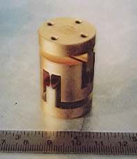
Figure 3.3 One of the 3 laminar suspensions used in the GGG experiment. High mechanical quality is obtained by careful manufacturing. The suspensions are carved out of a solid bar of CuBe and properly treated to ensure high quality. The design is such as to have high stiffness in the vertical direction (to withstand gravity) and at the same time very low stiffness in the horizontal plane, so as to improve the sensitivity of the instrument to small forces. These suspensions have been manufactured by "DG Technology", Parma, Italy according to our design. The "Eöt-Wash" group (Seattle, USA) has expressed an interest in using this type of suspension for their torsion balance experiments (Gundlach, 1998)
3.4 The Apparatus
In this section we give an overview of the GGG apparatus as it is at present.
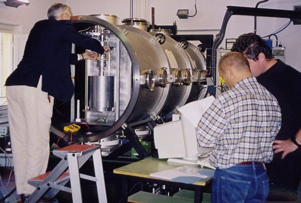
Figure 3.4 The rotor designed in Fig. 3.1 being mounted by Dr. D. Bramanti inside the vacuum chamber in the laboratory of Laben in Florence. The electronics was in part realized by QSA Srl, Arezzo
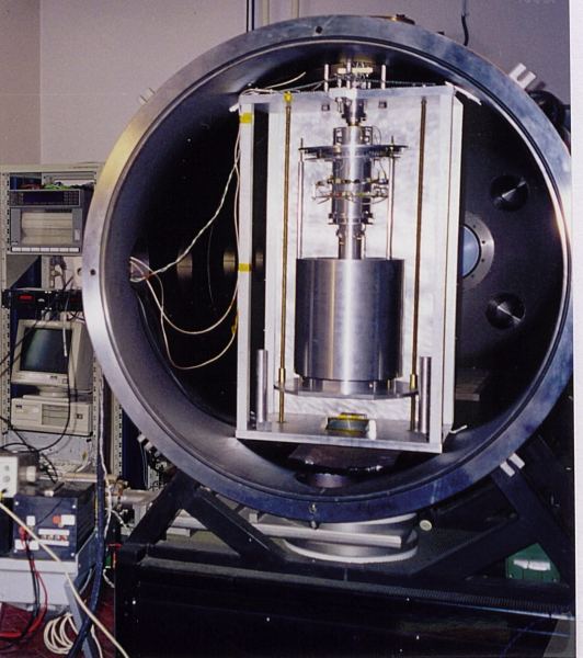
Figure 3.5 The GGG rotor inside the vacuum chamber with the electronics partially mounted. The technical drawings are from ProMec, Bientina (Pisa), and the main parts have been manufactured by CoMeBa, Pisa. Many components have been realized in the mechanical workshop of Laben.
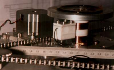
Figure 3.6 The motor used to spin the GGG rotor. It is a motor adapted for high vacuum by DG Technology Service, Parma. The sliding contacts are also visible. The chain is for holding and lifting the test cylinders during the assembling phase.
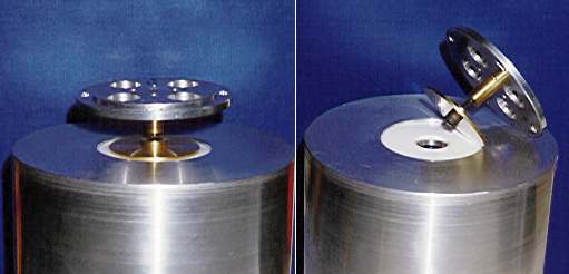
Figure 3.7 The passive damper used in the first tests. Friction between the polished brass disk and the teflon (white) one provides non rotating damping.
Figure 3.8 The passive damper currently in use; it is much lighter than the previous one and yet it is sufficient to stabilize the system because the required damping forces are very small. The brass disk of Fig. 3.7 has been replaced by a smaller and lighter disk (it is in light plastic at present). See Fig. 3.1 to identify where this damper is located in the apparatus (under the lowest laminar suspension).
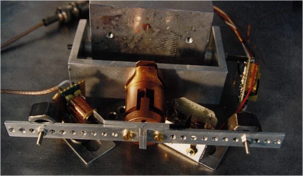
Figure 3.9 The GGG laminar suspension springs clamped and mounted for Q measurement in horizontal oscillations at a few Hz. The largest value obtained was 2,000; it improved at lower amplitudes but the measurements then became limited by seismic noise. Therefore, we expect their Q to be even better than our value measured in this way.
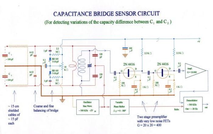 Figure
3.10 The capacitance bridge sensor circuits currently in use for the read out of the
relative displacements of the test cylinders. See Fig. 3.1 for their location in the GGG
apparatus
Figure
3.10 The capacitance bridge sensor circuits currently in use for the read out of the
relative displacements of the test cylinders. See Fig. 3.1 for their location in the GGG
apparatus
 Figure 3.11 Two-phase
synchronous demodulator circuits currently in use. They carry out the signal demodulation
required also in the space experiment and described in Fig. 2.21
Figure
3.12 A D conversion and IR transmission circuit. This is the
circuit used for digitizing the signal (A/D converter) and for driving the optical
emitter, located at the top of the shaft, in order to transmit the demodulated signal from
the rotor to the non rotating frame and then outside of the vacuum chamber.
Figure
3.13 Infrared receiver circuit and microprocessor for
receiving the demodulated, digitized, optically transmitted signal and have it ready for
analysis.
Figure 3.11 Two-phase
synchronous demodulator circuits currently in use. They carry out the signal demodulation
required also in the space experiment and described in Fig. 2.21
Figure
3.12 A D conversion and IR transmission circuit. This is the
circuit used for digitizing the signal (A/D converter) and for driving the optical
emitter, located at the top of the shaft, in order to transmit the demodulated signal from
the rotor to the non rotating frame and then outside of the vacuum chamber.
Figure
3.13 Infrared receiver circuit and microprocessor for
receiving the demodulated, digitized, optically transmitted signal and have it ready for
analysis.
The GGG test bodies have been mounted in a coupled (low stiffness) mechanical suspension and they have been balanced so as to reach long natural periods of differential oscillations; this means that they are sensitive to small differential forces acting in the horizontal plane. The whole system has been put in rotation reaching a spin rate of
10 Hz (in vacuum). The state of rotation is supercritical so that the centers of mass of the test cylinders once in rotation auto-center themselves on the rotation axis (hence with respect to one another) better than they had been centered because of manufacturing and assembling errors. A stepping motor modified for vacuum has been mounted.The laminar suspensions used to suspend the bodies and couple them have been verified to have high mechanical quality, i.e. low dissipation, under deformations at the spin frequency. They can withstand the weight of the bodies (
10 kg each) along the local vertical but have low stiffness in response to forces in the horizontal plane as it is required for EP testing. Losses in the suspensions generate unstable whirl motions of the rotating test cylinders at their natural frequency of differential oscillations. A light damper, non rotating and passive, has been built and has proved to be capable of stabilizing the system up to a spin frequency of 10 Hz (in vacuum). A first damper (Fig. 3.7) has been replaced by a much lighter one (Fig. 3.8) because the whirl motion to be damped is very slow, as predicted by the GG Team in agreement with experts in Rotordynamics (Crandall and Nobili, 1997). Work is in progress to replace the passive damper with an active and more controllable one, using electrostatic forces, as in the GG design. The required electronics has been manufactured but needs to be tested; the software to operate it is in preparation (Aversa, 1998).The test bodies coupled suspension has been balanced to
1 part in 200000 (in D m/m), which is better than the balancing level currently required for the GG test bodies in space (c CMR=1/100000, see Sec. 2.2.1). The capacitance sensors of the read out system have been manufactured and mounted. The electronics needed for the amplification, demodulation, digitalization and optical transmission of the signal outside of the rotor has been built and mounted on the rotor, and it is under testing (Figs. 3.10¸ 3.12). The sensitivity of the capacitance bridge has been measured (with plates of 200 cm2): it can detect relative displacements of 5 picometers in 1 sec of integration time and therefore only 100 sec of integration time are enough to reach the sensitivity required by the GG space experiment. With smaller plates (2 cm2) like those designed in GG for the active dampers it is easy to measure 100 Angstrom, as it is required for whirl control in space (see. Chap. 6).The system is operational; without the electronics of the read-out it spins stably between
2 and 10 Hz, with the test cylinders axes aligned on one another within 100 m m. It demonstrates that macroscopic weakly coupled and balanced rotors can be made to spin very stably and very well aligned. The electronics has been mounted and tested at zero spin rate. For supercritical rotation the electronics components themselves need to be carefully balanced; this work is underway and a sensitivity test will be carried out as soon as it has been completed.Theoretical work is in progress on gyroscopic effects and on differential effects of forces from nearby mass anomalies.
The contribution by Li-Shing Hou (from the research group led by Wei-Tou Ni, at the National Tsing Hua University) to the mounting and testing of GGG is kindly acknowledged.