6 Stabilization and Drag Free Control
6.1 Theoretical Analysis and Control Laws
Theoretical Analyisis and Control Laws
The complete GG system of
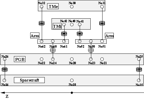
6 bodies has been simulated using DCAP (Dynamics and Control Analysis Package) software developed by Alenia Spazio under ESA contract. The dynamical model is schematically represented in Fig. 6.1. The 6 bodies of the model are defined as follows:
Figure 6.1 Planar 6-body model of the GG system with springs, gimbals and the related connections. The 6 bodies are: the spacecraft, the PGB laboratory, 2 test masses and 2 gimballed arms. The spin angular velocity of the spacecraft is around the Z-axis.
This type of multi-body connection grants an open-loop kinematics topology, with no need for cut-joint hinges. All hinges are described by a Euler sequence Type 1,
x-y-z. The active dofs (degrees of freedom) defined by hinges can be differently set depending on the type of simulation, i.e. a full 3D simulation including conical and cylindrical modes or a reduced 2D simulation with the cylindrical modes only.2D Simulation with Cylindrical Modes. The S/C, PGB and TMs have
x-y translational and z rotational dofs only, and no conical modes. The gimbals allow conical movements of the coupling arms around their midpoints .
Hinge |
Transl. Dofs (x,y,z) |
Rotational Dofs (x,y,z) |
1 ¸ 4 |
F, F, L |
L, L, F |
5 ¸ 6 |
L, L, L |
F, F, L |
Note : L=Locked F=Free |
||
3D Simulation Including Conical and Cylindrical modes. The S/C, PGB and TMs have
x-y-z translational and x-y-z rotational dofs. The gimbals allow conical movements of the coupling arms around their midpoints .
Hinge |
Transl. Dofs (x,y,z) |
Rotational Dofs (x,y,z) |
1 ¸ 4 |
F, F, F |
F, F, F |
5 ¸ 6 |
L, L, L |
F, F, L |
Note : L=Locked F=Free |
||
The mass properties used are consistent with the model used for the GG Pre Phase A Study (1996) and are recalled in Table 6.1. Two cases are analyzed for the gimballed arms: with and without a Pt/Ir ring respectively. In the first case they have Jp>Jt, while in the second they have Jp<Jt , that is, they would be unstable if isolated due to their pencil-like shape. The purpose is to determine whether the gimballed coupling arms inserted in the GG system (see Fig. 2.1) require rings for stabilizing the rotation or not. The result of this work (see Sec. 6.1.14) is that once the test masses are stabilized, also the coupling arms are (the test bodies are much more massive than the arms); therefore, rings are not needed, as it was predicted during the GG Pre Phase A analysis (1996).
| Item | Body ID |
Mass [ kg] |
Jt=Jx=Jy [kg× m2] | Jp=Jz [kg× m2] |
| S/C | 1 |
122.071 |
19.616 |
29.263 |
| PGB | 2 |
43.647 |
2.224 |
3.23305 |
| TMe | 3 |
10.0 |
0.0752 |
0.0754 |
| TMi | 4 |
10.0 |
0.0163 |
0.0165 |
| Gimballed arms w/o ring | 5 ¸ 6 |
2.18 × 10⁻² |
8.29 × 10⁻⁶ |
8.54 × 10⁻⁷ |
| Gimballed arms with ring | 5 ¸ 6 |
7.93 × 10⁻² |
7.81 × 10⁻⁶ |
8.39 × 10⁻⁶ |
Table 6.1 Mass Properties
6.1.2 Geometrical PropertiesThe geometrical data are set for a total PGB height of
0.7 m, a TMe height of 0.21206 m, a TMi height of 0.10603 m. The gimbal points on PGB have Z coordinate of ± 0.53015 m. The initial spring offset, i.e., the distance between bodies C.G. and spring mounting point is set to 1m m in x-axis for the S/C-PGB and/or PGB-TMs connections. Additional errors (mounting/mis-alignment) can be introduced in mounting points. The geometry for the DCAP nodes is summarized in Table6-2.Node ID |
Body ID |
X [m] |
Y [m] |
Z [m] |
10 |
1 |
0.0 |
0.0 |
0.0 |
15-16 |
1 |
1.0 × 10⁻⁶ |
0.0 |
± 0.35 |
20 |
2 |
0.0 |
0.0 |
0.0 |
21-22 |
2 |
0.0 |
0.0 |
± 0.10603 |
23-24 |
2 |
0.0 |
0.0 |
± 0.053015 |
25-26 |
1 |
0.0 |
0.0 |
± 0.35 |
30 |
3 |
0.0 |
0.0 |
0.0 |
31-32 |
3 |
0.0 |
0.0 |
± 0.10603 |
40-41-42 |
4 |
0.0 |
0.0 |
0.0 |
50 |
5 |
0.0 |
0.0 |
0.0 |
51-52 |
5 |
0.0 |
0.0 |
± 0.053015 |
60 |
6 |
0.0 |
0.0 |
0.0 |
61-62 |
6 |
0.0 |
0.0 |
± 0.053015 |
Table 6.2. Geometrical Properties of the GG system simulated with DCAP software. |
||||
The sensors in DCAP are a way to monitor the dynamic state of the system, performing an ideal measurement. A set of sensors has been defined both for active control and post-processing purposes.
6.1.4 Actuators and Function
Generators. Definition of External Disturbance
The external disturbance is defined in the following way. The referring orbit is a 520 km circular orbit in the equatorial plane, with orbital angular velocity w orb and orbital period Torb:
w
orb=1.102× 10⁻³ rad/sec =1.754× 10⁻⁴ Hz, Torb=5701.64 sec (6.1)For the purposes of the present analysis the orbital motion of the satellite can be neglected, and also the gravity gradients components; the orbiting reference system is therefore approximated by an inertial reference frame. The following scaling has been applied to the disturbances.
The residual drag disturbance (after Drag Free Control) has been set to
5× 10⁻⁹ N in order to study the effects of measurement noise. The disturbance signals are built up using DCAP function generators, which are interconnected to actuators in order to provide the requested forcing function. We have:The actuators in DCAP provide a way of exerting forces or torques on the system. A "jet" actuator is characterized by an application point and a direction for an external force.
The excitation level is introduced as interconnection gain. Six interconnects Int11
¸ Int16 are defined according to the following scheme.

Figure 6.2 Interconnects defining the drag force components x and y (with noise).
Devices in DCAP define stiffness and damping according to different models. A linear device connecting two nodes on one axis provides a restoring force proportional (
k) to the distance between nodes on that axis and (c) to the relative speed of the nodes on that axis. With similar definition, a device can be selected to be acting on a relative degree of freedom at hinge level. By convention, in the definition of DCAP items the rotational freedoms come first (x¸ z=1¸ 3) followed by the translational ones (x¸ z=4¸ 6). These forms allow us to define the elastic connections between bodies. With reference to the scheme of Fig. 6.1 we have:The local bending stiffness of springs is neglected, being overcome by the offset of mounting. Exception is made for the inner mass, where the connecting points are coincident (No40
º No41º No42).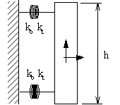
kb : rotational (bending) local stiffness
kt : translational stiffness
With respect to mid-point: ![]()
The corresponding numerical values are given in Table 6.3. As far as the damping coefficient is concerned, we must distinguish between
x,y translations, where the springs deform in supercritical rotation at rates close to the spin rate (w s-w k, w k<<w s), and z translation where instead springs deform at rate w k. Given a quality factor Qk of an oscillator of mass mk, spring constant k and natural frequency w k (in rad/sec), the damping coefficients are defined as:![]() for
subcritical motion (z). (6.2)
for
subcritical motion (z). (6.2)
![]() for
supercritical motion (x,y). (6.3)
for
supercritical motion (x,y). (6.3)
The damping coefficients are given in Table 6.3, having used QPGB=90 (the mechanical quality factor of the PGB suspensions) and QTM=500 (the mechanical quality factor assumed in this analysis for the suspensions of the test masses). Note that while QPGB=90 is the value measured experimentally for the suspension springs of the PGB, Q measurements for the suspension springs of the test masses have yielded values 16000¸ 19000 (see Sec. 2.1.5), i.e., much better than the value QTM=500 assumed here. The problem is that, with the measured values the whirl motions of the test masses grow so slowly (Eq. 2.20) that the numerical control would take far too long to stabilize the system. For this reason, in all the present analysis we assume a much poorer mechanical quality for the suspensions of the test masses (by a factor of 4); therefore, the simulations refer to a dynamical control problem more difficult than the control problem of the actual GG system.
Stiffness |
Damping |
|
| Translational (PGB) | kt=1.0 × 10⁻² N/m |
ctPGB=3.537 × 10⁻⁶ Ns/m |
| Translational (TMs) | kt=1.0 × 10⁻² N/m |
ctTM=6.366 × 10⁻⁷ Ns/m |
| Bending (PGB) | kb=1.0 × 10⁻⁷ Nm/rad |
cbPGB=3.54 × 10⁻¹¹ Nms/rad |
| Bending (TMs) | kb=1.0 × 10⁻⁷ Nm/rad |
cbTM=6.37 × 10⁻¹² Nms/rad |
| Torsional (PGB) | k y =1.9× 10⁻⁶ Nm/rad |
c y PGB=0 Nms/rad |
| Torsional (TMs) | k y =1.9× 10⁻⁶ Nm/rad |
C y TM=0 Nms/rad |
| Gimbals | k q =4.0× 10⁻⁶ Nm/rad |
c q =0 Nms/rad |
Table 6.3 Passive Devices Numerical Values (with QPGB=90, QTM=500). Note that we assume QTM=500, which is about 1/4 of the measured value, in order to make the whirl instability of the test masses grow faster so as to speed up the numerical simulations. The problem is easier if instabilities are slower, so our analysis is carried out under conservative assumptions.
Additional devices must be introduced for translations in z direction, without stiffness, defining the missing sub-critical damping. This can be done only at hinge level (
z translation, dof #6).All the set of devices described above define the passive elastic connections of the GG model.
6.1.6 Active Devices (User Defined)The implementation of active damping of whirling motion can be introduced in DCAP in different ways. We have chosen to add special devices ("user-defined" via Fortran routines), whose command is computed in the subroutines that implement the stabilization scheme will described in the following sections. These devices act in parallel to the passive ones for the supercritical dofs. A mnemonic identification number has been set, according to the following example.
De24 connects No15-25, i.e., Bo 1
¸ 2, in x direction. Using the hinge ID number to identify the connecting bodies (Hi2) and the dof ID number (x=4), the device number is 24. The additional user device is defined by adding a third digit (1), resulting in an ID number of 241. This rule becomes important in the user-defined routine which identifies the applicable dofs and application points relying on device ID number.A User-Defined Discrete Controller (USDC) with sampling rate of Ts /10 sec (with Ts the GG spin period) is defined to implement the stabilization logic and the related filtering processes. The controller adds errors to the measurements, performs filtering and computes the magnitude and phasing of the stabilization forces in the rotating frames; actuation of forces is executed by user-devices described above.
USDC has 3 inputs (relative displacements in x, see 6.1.8) and 22 outputs. The outputs are used mainly for checking purposes and for Drag Free Control. Details on USDC definition can be found in Section 6.2.
Besides the interconnects used to activate external disturbance (see Sec. 6.1.4), three additional interconnects are used to feed the controller with the relative displacement signals. In this first implementation, only one plate is used, assuming it to be aligned with x direction of inboard body. The nominal sensors measurements are fed to USDC with:
The easiest way to pass data to user defined routines is through "constant data" blocks. Each CNTDTA has an ID number and a value (double precision) associated to it. The following sets of data have been defined:
With the model set-up outlined in the previous sections, a linearization has been performed in order to determine the eigenfrequencies of the system. The eigenvalue problem has been solved for the zero-spin rate case (w s=0), in order to determine the whirling frequencies; linearization at non zero spin cannot be performed in DCAP and has been done with the DYNROT software by Prof. Genta and Dr. Brusa at Politecnico di Torino. We have checked that the results reported in Table 6.4 are essentially unchanged, as expected.
The complete model has 6 rigid-body dofs plus 22 flexible dofs (18 for the PGB. TMe, TMi plus 4 for the gimbals conical modes). The results are shown in Table 6.4; it can be noticed that the different configurations of the gimballed arms (with and without rings) do not affect the other frequencies; they obviously affect the local modes of the arms. If the gimbals are supposed to be mounted on a rigid fixture, with equivalent bending stiffness k’q given by
k’q =2kb+k× h2/2+kq @ k× h2/2+kq =0.01× 0.106032/2+4.0× 10-6=6.0212× 10⁻⁵ Nm (6.4)
and with the values for Jt given in Table 6.1, the eigenfrequencies are 85.22 and 87.81 rad/sec, thus confirming the local nature of these modes.
The configuration of gimballed arms without the stabilizing ring is expected to affect the test-masses differential modes with larger contributions. Any misalignment of the Jp axis w.r.t. spin axis is amplified by inertial moments, for a given q 0 initial out-of-phase angle if the configuration is unstable (Jp<Jt). Since the conical motion of the gimballed arms directly induces differential motion in the test masses, the two configurations have been analyzed in order to evaluate the effects on differential motion and define a baseline design. It is found that, due to the much smaller mass of the coupling arms compared to the mass of the test bodies which they couple, they are in fact stabilized once the test bodies themselves are stabilized by the active control of their whirl motions. Therefore, in the remainder of this Chapter, all the 6-body simulations refer to coupling arms without rings.
|
Without Pt/Ir Ring |
With Pt/Ir Ring |
|||||
# |
Freq. [rad/sec] |
Freq. [Hz] |
T [sec] |
Freq. [rad/sec] |
Freq. [Hz] |
T [sec] |
Type |
7 |
7.975E-4 |
1.269E-4 |
7878.50 |
7.975E-4 |
1.269E-4 |
7878.50 |
Rz PGB |
8 |
3.504E-3 |
5.577E-4 |
1793.15 |
3.504E-3 |
5.577E-4 |
1793.15 |
Rx Tmi |
9 |
3.504E-3 |
5.577E-4 |
1793.15 |
3.504E-3 |
5.577E-4 |
1793.15 |
Ry Tmi |
10 |
5.079E-3 |
8.084E-4 |
1237.09 |
5.079E-3 |
8.084E-4 |
1237.09 |
Rz Tme |
11 |
1.076E-2 |
1.712E-3 |
583.99 |
1.076E-2 |
1.712E-3 |
583.99 |
Rz Tmi |
12 |
1.153E-2 |
1.835E-3 |
545.08 |
1.153E-2 |
1.835E-3 |
545.08 |
DIFFERENTIAL x |
13 |
1.153E-2 |
1.835E-3 |
545.08 |
1.153E-2 |
1.835E-3 |
545.08 |
DIFFERENTIAL y |
14 |
2.125E-2 |
3.383E-3 |
295.64 |
2.125E-2 |
3.383E-3 |
295.64 |
Tx PGB |
15 |
2.125E-2 |
3.383E-3 |
295.64 |
2.125E-2 |
3.383E-3 |
295.64 |
Ty PGB |
16 |
2.125E-2 |
3.383E-3 |
295.64 |
2.125E-2 |
3.383E-3 |
295.64 |
Tz PGB |
17 |
3.339E-2 |
5.315E-3 |
188.15 |
3.339E-2 |
5.315E-3 |
188.15 |
Rx PGB |
18 |
3.339E-2 |
5.315E-3 |
188.15 |
3.339E-2 |
5.315E-3 |
188.15 |
Ry PGB |
19 |
4.195E-2 |
6.676E-3 |
149.79 |
4.195E-2 |
6.676E-3 |
149.79 |
Rx Tme |
20 |
4.195E-2 |
6.676E-3 |
149.79 |
4.195E-2 |
6.676E-3 |
149.79 |
Ry Tme |
21 |
4.472E-2 |
7.118E-3 |
140.50 |
4.472E-2 |
7.118E-3 |
140.50 |
DIFFERENTIAL z |
22 |
5.556E-2 |
8.843E-3 |
113.09 |
5.556E-2 |
8.843E-3 |
113.09 |
COMMON x |
23 |
5.556E-2 |
8.843E-3 |
113.09 |
5.556E-2 |
8.843E-3 |
113.09 |
COMMON y |
24 |
5.556E-2 |
8.843E-3 |
113.09 |
5.556E-2 |
8.843E-3 |
113.09 |
COMMON z |
25 |
8.522E+1 |
1.356E+1 |
0.0737 |
8.783E+1 |
1.398E+1 |
0.0715 |
Gimballed arm 1 x |
26 |
8.522E+1 |
1.356E+1 |
0.0737 |
8.783E+1 |
1.398E+1 |
0.0715 |
Gimballed arm 1 y |
27 |
8.522E+1 |
1.356E+1 |
0.0737 |
8.783E+1 |
1.398E+1 |
0.0715 |
Gimballed arm 2 x |
28 |
8.522E+1 |
1.356E+1 |
0.0737 |
8.783E+1 |
1.398E+1 |
0.0715 |
Gimballed arm 2 y |
Table 6.4 Eigenfrequencies of the GG 6-body system at zero spin rate as computed with DCAP.
6.1.11 Whirling StabilizationThe stabilization of whirl motion (see Sec. 2.1.5 for a physical introduction) can be implemented by building in a rotating frame a damping command proportional to the relative velocity between bodies in the inertial (non-rotating) reference frame. A simple way to show this capability is by examining the problem of 2 bodies connected by a dissipative spring. Let us consider rs the vector pointing to the Spacecraft center of mass, rp the vector pointing to the PGB center of mass, e the vector locating the suspension point of the spring with respect to the Spacecraft center of mass, S the Suspension point of the spring (see Fig. 6.3). The spacecraft is rotating around the z-axis, which is perpendicular to the xy plane. The rotation is counter-clockwise. In the inertial reference frame the equations of motion read:
 (6.5)
(6.5)
being e = e (t) a rotating vector in the inertial frame (fixed in the reference frame corotating with the spacecraft) and ws the spin angular velocity. These equations show clearly the nature of rotating damping, namely damping between the rotating bodies. Using: x = rp - rs (relative position vector); mr = ms mp /(ms + mp) (reduced mass), w 02= k/mr (natural frequency of oscillation), cr = k/(Qw s) (coefficient of rotating damping, with Q the mechanical quality factor of the spring), we can write the equation for the relative motion of the two bodies:
![]() (6.6)
(6.6)
The solution of the equation of relative motion is:
 (6.7)
(6.7)
with:
Figure 6.3 Schematization of the two-body model problem.
 (6.8)
(6.8)
the vector describing the displacement of the equilibrium position due to the action of the external drag and xwhirl (w wt) the exponential term giving rise to the spirals shown in Fig. 6.4.
Figure 6.4 Simulation of the 2-body system with and without an external residual drag. It shows how the effect of an external force (e.g. air drag) is that of displacing the equilibrium position of the system. A small phase lag appears due to energy losses in the suspensions (finite Q), as expected. Due to these losses the whirl instability builds up in either case around the corresponding equilibrium position.The 2-body system is unstable. The simplest way to stabilize it is adding some Non Rotating Damping (i.e. damping between non rotating parts of the system), which is mathematically expressed by the terms containing Cnr (the equations refer again to the inertial reference frame):
 (6.9)
(6.9)
![]() (6.10)
(6.10)
These equations are useful to see the difference between Rotating Damping (term with cr), and Non Rotating Damping (term with Cnr, which is the number defined by Cn 2 - Cn 4); see Fig. 2.16 for a physical explanation. In the space experiment everything is corotating with the spacecraft, so we need to recast these equations in the rotating reference frame:
 (6.11)
![]() (6.12)
(6.12)
with ![]() and
and ![]() the relative displacement and its rate of
change in the rotating reference frame. The minimum Cnr for stabilizing
the whirling motion is Cnr = cr w /w 0.
the relative displacement and its rate of
change in the rotating reference frame. The minimum Cnr for stabilizing
the whirling motion is Cnr = cr w /w 0.
6.1.12 Whirling Stabilization Control Law
We have seen in the previous Section that the stabilization of whirl motion can be implemented by building in the rotating frame a damping command proportional to the relative velocity between the bodies in the inertial (non-rotating) reference frame
![]() (6.13)
(6.13)
A more compact complex notation can be used by replacing the vector with a complex number (z =x +ih ) and the cross product operator w s´ by iw s (i=Ö -1), giving
![]() , (6.14)
, (6.14)
all in the rotating frame. Conversely, if ![]() is the displacement in the inertial frame, the relative velocity in
rotating frame, on which rotating damping acts, can be defined as
is the displacement in the inertial frame, the relative velocity in
rotating frame, on which rotating damping acts, can be defined as ![]() .
.
The main drawback of a continuous approach is that the whirl motion builds up with long time constants, and consequently the rate of change of the relative amplitude is highly dominated by the measurement noise. The tangential component of the stabilization signal instead must be built from the difference of two large terms, i.e., (w s-w n)t and w st, affecting the phasing of the compensation command. Furthermore, any bias in the measurement is amplified by the pre-multiplication of w s.. A modified approach based on signal filtering has therefore been introduced.
Let us see the solution of the equation motion (relative displacement of the bodies) in the rotating reference frame; in absence of non rotating damping it reads:
 (6.15)
The first term is a fixed vector in the rotating reference frame which depends on the initial offset of the mounting point of the springs; the second term is a vector corotating with the drag force (with the angular velocity w s as seen in the rotating frame) and with a phase lag f with respect to the drag depending on the mechanical quality factor of the spring, tan(f ) = 1/Q; we have assumed a drag defined by a DC component plus a term at orbital frequency in the inertial reference frame, so, zdrag(t) has w s and (w s-w orb) angular frequencies (in the rotating reference frame). The third term, describing the growing spiral of the whirl motion, has (w s-w w) angular frequency. The idea is of using the precise signature of the growing whirling motion to build a control law capable of stabilizing the system. The starting point is sampling the relative displacement signal within every spin period Ts, with N points, and to analyze the harmonic at Ts in order to reconstruct the modulating signal amplitude and phase: note that in this way any bias is removed (it is a constant additional term of z(t)). Given N sampled points of the displacement z(t) in the spin period interval Ts=w s/2p :
 (6.16)
the fundamental harmonic can be obtained from Fourier integral as
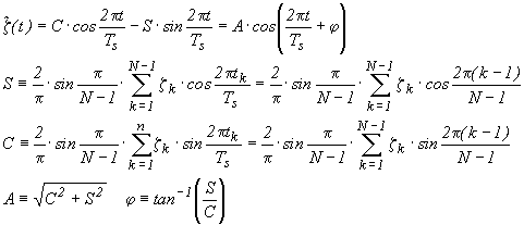 (6.17)
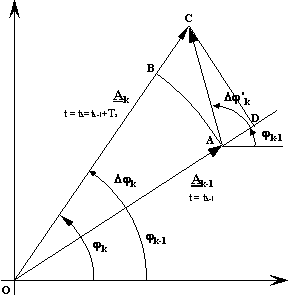
From the difference between the corresponding values in two spin periods, the velocity of the modulating signal is then reconstructed. We obtain in fact a pair of values (Ak, j k) for each spin period. The first harmonic filtered amplitude Ak and phase j k can be used with Ak-1, j k-1 at previous step (tk-1=tk-Ts) to determine the relative velocity in the inertial frame. The velocity signal Vk and its phase j Vk are determined according to the following sketch.
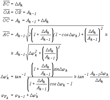 (6.18)
The estimated amplitude (Ak, j k) and velocity information (Vk, j Vk) will be delayed by one revolution (Ts), since one Ts is needed to sample the starting data. Moreover, no velocity can be estimated in the first two spin periods of the simulation. The following formulas will apply:
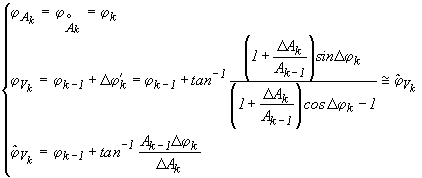 (6.19)
and
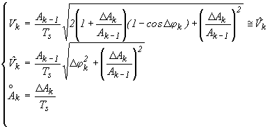 (6.20)
A number of 11 points over Ts has been found to be a good compromise in treating noisy signals. The implemented discrete sampler is in fact operating at 10/ Ts Hz.
The simplified analysis for a two-body system shows that the reconstructed velocity is predominantly driven by the noise. This can be easily understood: the whirl motion grows so slowly that its velocity cannot possibly be estimated with good accuracy by analyzing variations in just one spin period of 0.5 sec. Therefore, in order to improve the resolution of the forces the natural solution is to perform a second Fourier harmonic analysis at the whirl period Tw. This is feasible thanks to the following fact.
The solution to the eigensystem for uncontrolled whirling of a system with high quality factor can be simplified to ± (w n/2Q)± i× w n; the ratio of the time constant for the divergent forward whirling mode to the whirling period is therefore Q/p , i.e., the time-to-double is 0.32× Q times larger than Tw. By using a Q=90 for the PGB, and its natural period of 296 sec, the signal doubles in » 28.6× Tw (2.4 hours). This suggests that there is enough time to collect samples over the whirl period and run the filter extracting an approximate sinusoidal signal that will be very close to the marginally divergent real signal. Even if the driving velocity signal will be applicable to previous period and the whirling will have increased, we must recall that we are handling a "stabilization" problem, where a minimum gain grants stability; therefore, a slightly larger margin on the gains completely overrides the problem. Note that Q=90 is the lowest Q in the GG system; hence this is the fastest growing whirl instability and therefore the most difficult to handle.
The formulas for this second harmonic analysis are the same of the first Fourier filter, after substituting Ts with Tw and zk(tk) with the discretised velocity along the x and y axes. An example of the capability of this double-filter control is shown in the following pictures. A sample of 1000 sec of simulated evolution of the 2-body system S/C-PGB has been considered first in the ideal condition (perfect reading and actuating sensors), then in a realistic situation (imperfect sensors). A residual drag of 5 10-9 N DC plus 2× 10⁻⁹ N at orbital frequency, with 10% noise on both components, a mechanical quality factor Q = 90, and a non Rotating damping coefficient have been used in both the simulations; the spinning frequency is n s = 2 Hz. Figures 6.5¸ 6.8 show the results obtained in reconstructing the slow whirl velocity to be damped and demonstrate the validity of our strategy in the 2-body model case (both ideal and with realistic error sources; see Chap. 3 for experimental results on the accuracy of capacitance sensors).
Figure 6.5 Actual relative displacement S/C-PGB in the inertial frame as predicted with DCAP, to be compared with the relative displacement as reconstructed by the controller from measurements of the rotating sensors after the first Fourier filter (
ws filter, dashed curve); case of ideal, perfect, sensors.Figure 6.6 Actual relative displacement S/C-PGB in the inertial frame as predicted with DCAP, to be compared with the relative displacement reconstructed by the controller from measurements of the rotating sensors after the first Fourier filter (
ws filter). The errors included were: errors on sensors RMS = 10-2 m m, bias = 10 mm, angular bias = 1o, RMS(w) = 10-4 w. The bias has been removed from the sensor signal curve due to the scale (10 mm vs 10-7 m). The improvement due to the Fourier filter is apparent: The bias is cancelled out, the RMS is partially filtered out.
Figure 6.7 Actual relative velocity S/C-PGB in the inertial frame, as predicted with DCAP, to be compared with the relative velocity as reconstructed by the controller after the second Fourier filter (
ww filter): case of ideal, perfect, sensors. Figure 6.8 Actual relative velocity S/C-PGB in the inertial frame as predicted with DCAP, to be compared with the relative velocity as reconstructed by the controller after the second Fourier filter (ww filter). The errors included were: errors on sensors RMS = 10-2 m m, bias = 10 mm, angular Bias = 1° , RMS(w) = 10-4 w. Note that, to the scale used, this figure is identical to the previous one, obtained with no errors; only by computing the difference of the velocities reconstructed in the two cases it is found that they are not identical. This result is very important. It shows the effectiveness of applying a second Fourier filter at the frequency of whirl in order to get rid of noise caused by error sources in the reconstruction of the whirl velocity; an accurate reconstruction of the whirl velocity is essential in order to be able to damp it without introducing large, spurious disturbances. 6.1.13 Non Rotating Damping in Pulsed ModeThe continuous compensation described in Sec. 6.1.12 requires a stabilization force to be operated by the active plates in the form of a sinusoidal signal . An equivalent scheme, based on pulsed operation, has been conceived and implemented.
![]() (6.21)
(6.21)
or, in Laplace domain (operator s) and complex notation ![]() ,
,
![]() (6.22)
(6.22)
In order to limit the noise amplification due to the derivative term and the amplification of displacement readout biases through the w s term, the integral estimate of velocity and pulsed command mode are introduced. The attracting force is applied in the form of sinusoidal pulses of width ± p /4 across velocity phase (j V+p ), with two pulses in one turn, one for each actuator as in the sketches shown next page. The pulses must be sized 2× CNR× |V| in order to provide the equivalent stabilization of the continuous command. In the reference frame of the spacecraft, with the phase reference (t0) given by sensor plate S1, the required control forces are:
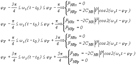 (6.23)
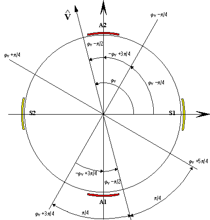
The velocity vector V with the reference sensor S1, and the actuators devices A1 and A2.
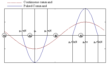
Definition of the whirl
stabilization command in pulsed mode.6.1.14 2-Body and 6-Body Results
In this Section we apply the control laws in order to damp whirl motions in the 2-Body model case made by the PGB laboratory and one test mass (PGB-TM) and in the full 6-body GG system. In both cases we first we assume using ideal, perfect sensors, and then introduce realist errors as follows:
e
= 1 m m (initial offset of the spring) w s = 2 Hz, k = 0.02 N/m, Q = 500, CNR = 0.009 Ns/m. Note that this value for the coefficient of non rotating damping CNR is about 11 times larger than the minimum value required for stability. This allows us to damp the system more rapidly, hence saving CPU time; the smallest coefficient we have tested was a factor 2.5 larger than the minimum and was enough to stabilize the system. The residual drag acting on the PGB has a DC component equal to 1.72 10-9 N; plus an orbital frequency term which is 40% of the DC component and a 10% of noise on both components (which are the scaled values of the 6-body system). All plots are shown in the non rotating frame.Figure 6-9 One day simulation of the 2-body PGB-TM system showing their relative distance (ideal case). Oscillations at orbital period are due to the oscillating term of the drag; the offset from the X axis is due to the DC term of the drag which displaces the equilibrium position of a fixed vector along X. The short period oscillations (see Fig. 6.10 for a close up), represent the whirl motion and decay in few thousand seconds.
This test of the ideal case was an important check of the principles of the whirl control: the results are in perfect agreement with the theoretical predictions, confirming the validity of the control law.
Figure 6.10 Short sample from the one-day simulation of the ideal 2-body PGB-TM system shown in Fig. 6.9: the rapid decay (over a few thousand seconds) of the short periodic whirl oscillations is apparent.
Figure 6.11 Sample of 15000 sec from the one day simulation of the ideal 2-body PGB-TM system shown in Fig. 6.9. This polar plot shows the approaching of the test mass to its ideal "equilibrium circle" caused by the residual drag force, and corresponding to a non dissipating spring (no whirl motion, infinite quality factor). The constant displacement along the X axis is caused by the DC term of air drag.
Figure 6.12 One day simulation of the ideal 2-body PGB-TM system as in Fig.6.9. Here we plot the whirl radius, which reduces to one or two Angstrom after 6000-7000 sec only.
Figure 6.13 One day simulation of the ideal 2-body PGB-TM system as in Fig. 6.9. Here we plot the passive elastic force of the spring for comparison with the active force of the control. Note that in these simulations the active force was taken to be 11 times larger than the minimum value required to provide stability, so as to speed up the simulations. We have checked that a force only 2.5 times larger than the minimum does stabilize the system, obviously less rapidly.
We now introduce realistic noise sources as listed at the beginning of this Section.Figure 6.14 One day simulation of the 2-body PGB-TM system with realistic error sources. Oscillations at orbital period are due to the oscillating term of the drag; the offset from the X axis is due to the DC term of the drag which displaces the equilibrium position by a constant amount along X. The short period oscillations (see Fig. 6.15 for a close up) represent the whirl motion and decay in few thousand seconds.
Figure 6.15 Sample from the one-day simulation of the realistic 2-body PGB-TM system as in Fig. 6.14. The short period oscillations are the whirl oscillations, which decay in a few thousand seconds.
Figure 6.16 Sample of 15000 sec from the one day simulation of the realistic (noisy) 2-body PGB-TM system as in Fig. 6.14. This polar plot shows the approaching of the test mass to the ideal "equilibrium circle" due to the variations of the residual drag force, and corresponding to a non dissipating spring (infinite quality factor, no whirl motion). Note that the scales on the two coordinate axes are different (the zero whirl "circle" is therefore distorted).
Figure 6.17 One day simulation of the realistic (noisy) 2-body PGB-TM system as in Fig. 6.14. Here we plot the whirl radius, which reduces to a few Angstrom after 7000-8000 sec only.
Figure 6.18 One day simulation of the realistic (noisy) 2-body PGB-TM system as in Fig. 6.14. Here we show the passive elastic force of the spring for comparison with the active force of the control. We recall that, in order to speed up the simulations, we apply an active force 11 times larger than the minimum needed for stabilization, and that an active force only 2.5 times larger than the minimum has been tested and found to be sufficient.
The 2-Body PGB-TM results show an impressive agreement between the ideal case and the case with realistic errors. We are therefore led to apply the same control laws to the full
6-Body GG system, both in 2 and in 3 dimensions. We have: ms/c = 122.071 kg, mPGB = 43.647 kg, mTM = 10 kg, w s = 2 Hz, k = 0.02 N/m, QPGB = 90, QTM = 500, CNR(PGB) = 0.05 Ns/m, CNR(TM) = 0.009 Ns/m (as above, this is about 11 times larger than the minimum value required for stability). The residual drag acting on the spacecraft has a DC component equal to 5 × 10⁻⁹ N plus an orbital frequency term which is 40% of the DC component and a 10% noise on both components. We have compared the ideal case (perfect sensors) with a realistic case where:All plots are shown in the non rotating frame. The gimballed arms were modeled without rings (see Sec. 6.1.10).
Figure 6.19 Ideal 6-body GG system. Simulation of 15000 sec. The figure shows the distance between the PGB and the spacecraft, and the distance between the external test mass and the PGB. There are three types of oscillations: one is at the orbital period, due to the component of the drag at this frequency, another is at the whirl period of the PGB (controlled), and the one with the shortest oscillation period is the controlled whirl motion of the test mass. The offset of the distances with respect to the X axis is due to the DC component of the drag force.
Figure 6.20 Ideal 6-body GG system. Polar plot showing the motion of the PGB and of the external test mass with respect to the center of mass of the spacecraft (0,0) during the first orbit (6000 s). The whirl motions start to be damped, but still need some time. Note that the scales on the two coordinate axes are different (the zero whirl "circle" is therefore distorted)
Figure 6.21 Ideal 6-body GG system. Polar plot showing the motion of the PGB and of the external test mass with respect to the spacecraft center of mass (0,0) during 9000 sec after the first orbit. It is now apparent that the whirl motions are damped and that the bodies are already very close to their zero-whirl orbits (the circles in this polar plot)
Figure 6.22 Ideal 6-body system. Here we plot the whirl radii of the PGB and of the external test mass for the same time interval as in Fig. 6.21.
Figure 6.23 Ideal 6-body GG system. Here we plot the passive elastic force for comparison with the active control force in the case of the external test mass. The value of CNR , the coefficient of non rotating damping applied to the test body, is 0.009 Ns/m, which is about 11 times larger than the minimum required value. A force 2.5 times larger than the minimum was found to be sufficient.
Figure 6.24 Ideal 6-body GG system with all degrees of freedom (3D simulation). No sensor noise applied (ideal case). The residual drag amounts to 5
× 10-9 N (DC), and 2× 10⁻⁹ N at orbital frequency (Torb=5701.64 s), with 10% noise. It is applied only in the xy plane; there is no external forcing term acting along the z-axis. As compared to the planar case, the additional degrees of freedom are shown not to produce any changes in the dynamics. However, the required computing time is much bigger, particularly if sensor noise is taken into account.Figure 6.25 The 6-body GG system with noise as given in the text.. Simulation of 12000 sec. The figure shows the distance between the PGB and the spacecraft and the distance between the external test mass and the PGB. As usual, there are three types of oscillations: one at the orbital period, due to the orbital component of the drag (the longest period), another with the whirl period of the PGB (controlled), and an even shorter one at the whirl period of the TM (also controlled) .The offset of the distances with respect to the X axis is due to the DC component of the drag force.
Figure 6.26 The 6-body GG system with realistic noise (see text). This polar plot shows the motion of the PGB and of the external test mass with respect to the center of mass (0,0) of the spacecraft for 9500 sec after the first 2500 sec.
Figure 6.27 The 6-body system with realistic noise (see text). We plot the whirl radius of the PGB and of the external test mass after the first 4000 sec. These values are in very good agreement with the theoretical predictions and the expected self centering.
Figure 6.28 The 6-body GG system with realistic noise (see text). Here we plot the passive elastic force of the spring for comparison with the control force acting on the external test mass. The value of the CNR coefficient of non rotating damping applied to the test body is 0.009 Ns/m, which is about 11 times larger than the minimum required value. We have checked that an active force only 2.5 times larger than the minimum could stabilize the system.
Figure 6.29 The 6-body GG system with realistic noise (see text). Here we plot the relative displacement between the inner and the outer test mass (differential displacement) obtained after applying the active control of their whirl motions as outlined in the previous sections (by double Fourier analysis). Note that in this simulation the whirl control is always on, i.e. this is a worst case simulation because whirl control can in fact be switched off during scientific data acquisition (see Sec. 2.1.5). Yet, this result is impressive in that it shows how active control by means of electrostatic sensors/actuators can be so accurate as to make the GG test bodies (macroscopic rotors of 10 kg each) self-center on one another as expected in supercritical rotation in absence of dissipation (infinite mechanical quality factor, zero-whirl). Achieving such a small separation of the test bodies is very important in order to reduce classical disturbing effects (such as Earth tides). Note that - although very small indeed- this relative displacement is still 160 times larger than the one expected in case of an EP violation to the level of 1 part in 1017 (see Eq. 2.2), which is the target of the GG mission. However, in the non-rotating reference frame (as in Fig. 6.26) the signal appears - after synchronous 2-phase demodulation at the 2 Hz spinning frequency- as a constant displacement always along the direction to the center of the Earth (indicated as the Y axis in Fig. 6.26 and as the X axis in Fig. 2.21); to the contrary, the whirl motion (shown in Fig. 6.26) which gives rise to the separation plotted here as function of time, has a distinct frequency, namely the natural frequency of the whirl (as it is apparent). This allows us to separate the relative displacement signal.
In summary, this work demonstrates that the whirl control problem of the complete GG system can be solved in realistic conditions. It is worth stressing that the results obtained in the presence of noise sources are especially good for the test masses because, while in the ideal case the active control force is, by the definition the same on both of them (common mode), this is obviously no longer the case when noise is introduced; it is therefore a very good feature of the controller designed here that of being able to avoid the onset of any spurious differential force between the test bodies. Having achieved the results shown in Fig. 6.29, it is possible to proceed to the recovery of the expected EP signal as discussed in Sec. 2.1.7, Fig. 2.21
6.1.15 Drag Free Control
So far we have applied the active control of whirl motions in the presence of a residual drag force assuming that air drag acting on the spacecraft has already been compensated. This is the task of the drag-free control. In this Section we present our current design for the Drag Free Control (DFC) of the GG satellite and test it in combination with the control of whirl motions. We do so first in the
2-body model PGB-Spacecraft and then in the full 6-body model of GG, both in the case of ideal, perfect sensors and in the case of realistic errors. The basic features of the GG drag free control are: (6.24)
with w
orb =2p n orb and V the "damping" of the DFC, which describes its bandwidth; x(s) is the relative displacement in the inertial reference system.The results are shown in the following figures; all plots are in the inertial (not rotating) frame of reference. The whirl control is always on, although the time-span of the simulation is always too short - given the initial very high level of drag- for the whirl motions to be damped; here the relevant issue is whether the DFC is effective in reducing the amplitude of the effect of drag at the orbital frequency, which it is.
Figure 6.30 Simplified model of the drag force used in the simulations of the DFC: drag along the x axis
Figure 6.31 Theoretical relative displacement between the PGB and the spacecraft (2-Body model) without (continous curve) and with (dashed curve) the application of drag free control; (ms=122.07 kg, mp=63.647 kg,
ns=2 Hz, Q=90).Figure 6.32 Relative displacement in the PGB-Spacecraft 2-body model with DFC applied (data as in Fig. 6.31) and the addition of some error sources as follows: RMS(capacitance sensor)=10-2 m m, Bias(capacitance sensor) =10
mm, Angular Bias(capacitance sensor) = 1o, RMS(w) = 0. Drag = 1.5 10-5 N at orbital frequency (Torb=5701.64 s) in the inertial reference frame, with 10% noise. The reduction of the amplitude of the displacement at the orbital frequency has been tested also with larger values of Drag (1.5 10-4 N ). In this simulation FEEP thrusters and Earth sensors are assumed to be perfect (no error).Figure 6.33 A detail from the previous plot showing how the drag free control is effective in reducing the amplitude of the relative displacement in just a few orbital periods of the satellite around the Earth.
Figure 6.34 Relative displacement in the PGB-Spacecraft 2-body model with DFC applied and the addition of noise sources as follows: RMS(capacitance sensor)=10-2 m m, Bias(sensor) =10
mm, Angular Bias(sensor) = 1o, Earth Elevation Sensor RMS(w) = 10-5 w, RMS(FEEP) = 5× 10⁻⁹ N (at 20 Hz), BIAS(FEEP) = 5× 10⁻⁹ N. Drag = 1.5 10-5 N at orbital frequency (Torb=5701.64 s) with 10% noise.Figure 6.35 Same as the previous plot except for the error assumed for the Earth Elevation Sensor, now a factor of 10 worse than in Fig. 6.34: RMS(
w)=10-4wFigs. 6.34 and 6.35 show the dependence of the DFC performances from the sensitivity of the Earth Sensor: this is due to the last operation of the DFC, which needs to transform the force from the inertial to the rotating frame where the actuators (FEEP) operate. The following figure shows the result of the simulation for the 6-body GG system, indicating that the DFC works just as well as in the 2-body case, save for the fact that it is much more demanding in terms of CPU time needed to run the simulations. Therefore, in the full system we have used the lower Earth sensor noise in order to show a significant reduction of drag already in first 2 orbital periods. Our purpose was to show that the current design of the DFC is adequate to reduce drag at the orbital frequency.
Figure 6.36 The GG 6-body system simulated with DFC for about two orbital periods. The noise sources applied are: RMS(sensor)=10-2 m m, Bias(sensor) =10
mm, Angular Bias(sensor) = 1o, Earth Sensor RMS(w) = 10-5 w, RMS(FEEP) = 5 10-9 N (at 20 Hz), BIAS(FEEP) = 5 10-9 N. Drag = 1.5 10-5 N at orbital frequency (Torb=5701.64 s) with 10% of noise. The purpose of the DFC is to reduce drag at the orbital frequency (the short periodic whirl oscillations are not relevant at this point and they are taken care of by the whirl controller): it is apparent from the PGB-Spacecraft curve that the amplitude of the oscillation at the orbital period (caused by drag) has been significantly reduced. As for the test mass, note that the curve giving its displacement from the PGB has been shifted by -2× 10⁻⁴ m in order to avoid it being hidden by the previous one. In this case too the amplitude of the oscillation at the already after 1 is reduced by the DFC.In summary, the DFC fulfils the scientific requirements of the GG mission. Although longer numerical simulations are needed, including partial drag compensation also along the spin/symmetry axis, we see no obstacles. It is also not a problem to add notch filtering at other frequencies (e.g. the second harmonic of the orbital drag…). However, it has been found that the performance of the DFC depends heavily on the knowledge of the spin rate: (Earth Sensor RMS(
ws)). The requirement on the RMS(ws) cannot be relaxed beyond 10-4 ws, which appears to be doable (see Sec. 5.5, p.138).