Proceedings of:
1999 NASA/JPL International Conference on FUNDAMENTAL PHYSICS IN SPACE
April 29,30 and May 1, Washington DC, NASA Document D-18925 (2000) pp.
309-327
Paper ready to print (pdf file, 625 Kb)
"GALILEO GALILEI" (GG)
Proposed Space Experiment to Test the equivalence Principle
and
Preliminary Results from the Prototype on the Ground
by
A.M. Nobili1, D. Bramanti1, E. Polacco1,
I.W. Roxburgh2, G. Comandi1, A. Anselmi3
G. Catastini3, A. Lenti4 and A. Severi5
1 Università di Pisa, Italia
2 Queen Mary and Westfield College, London, UK
3 Alenia Spazio, Torino, Italia
4 Laben, Milano, Italia
5Laben, Divisione Proel, Firenze, Italia
Contents
Abstract
1. Brief History of Equivalence
Principle Tests: a Quest for Higher and Higher Signal Frequency Modulation
2. Main Features and Novelties of the Proposed GG Experiment in Space
2.1 High
frequency modulation of the expected signal
2.2 Why work at room temperature
2.3 Weak mechanical coupling of the test bodies
and passive electric discharging
2.4 Dissipation, whirl motions and their
stabilization
2.5 GG error budget
3. Preliminary Results from the "Galileo Galilei on the
Ground" (GGG) Prototype
3.1 The GGG apparatus
3.2 Preliminary
measurements
Acknowledgements
References
"GALILEO GALILEI" (GG) is a proposal for a small, low orbit satellite devoted to testing the Equivalence Principle (EP) of Galileo, Newton and Einstein. The GG Report on Phase A Study recently carried out with funding from ASI (Agenzia Spaziale Italiana) concludes that GG can test the Equivalence Principle to 1 part in 1017 at room temperature. The main novelty is to modulate the expected differential signal of an EP violation at the spin rate of the spacecraft (2 Hz). As compared to other experiments, the modulation frequency is increased by more than a factor 104, thus reducing 1/f (low frequency) electronic and mechanical noise. The challenge in this field is to fly an experiment able to improve by many orders of magnitude the current best sensitivity (of about 1 part 1012). This requires spurious relative motions of the test bodies to be greatly reduced, leaving them essentially motionless. Doing that with more than one pair of bodies appears to be an unnecessary complication. This is why GG is now proposed with a single pair of test masses. At present the best and most reliable laboratory controlled tests of the Equivalence Principle have been achieved by the "Eöt-Wash" group with small test cylinders arranged on a torsion balance placed on a turntable which provides the modulation of the signal (at 1¸ 2 hr rotation period). Unfortunately, the torsion balance is not a suitable instrument in space. We have designed and built the GGG ("GG on the Ground'') prototype. It is made of coaxial test cylinders weakly coupled (via mechanical suspensions) and fast rotating (6 Hz achieved so far); in addition, it is well suited to be flown in space - where the driving signal is about 3 orders of magnitude stronger and the absence of weight is very helpful- inside the coaxial, co-rotating GG cylindrical spacecraft. The GGG apparatus is now operational and we report here some preliminary measurement data. They indicate that weakly coupled, fast spinning macroscopic rotors can be a suitable instrument to detect small differential effects. Rotation (up to 6 Hz) is stabilized by a small passive oil damper. A finer active damper, using small capacitance sensors and actuators as in the design of the space experiment, is in preparation. Then we shall have to deal with perturbing effects such as seismic noise and tidal tilting; e.g. by adding a passive cardanic suspension of the entire system and, if necessary, also with an active isolation from seismic noise based on capacitance sensors and piezoelectric actuators. As for the capacitance read-out, the current sensitivity (5 picometer displacements in 1 sec integration time, working at room temperature) is adequate to make GGG competitive with the torsion balance. Because of the stronger signal and weaker coupling of the test rotors in space, this sensitivity is also adequate for GG to reach its target (1 part in 1017). Information, references, research papers and photographs of the apparatus are available on the Web (http://tycho.dm.unipi.it/nobili).
1. Brief History of Equivalence Principle Tests: a Quest for Higher and Higher Signal Frequency Modulation Do bodies of different composition fall with the same acceleration in a gravitational field? If not, the so called Equivalence Principle -the founding pillar of General Relativity- is violated. The driving signal of a possible EP violation in the gravitational field of the Earth is about 3 orders of magnitude stronger than on Earth if the test bodies move in low Earth orbit. Since the expected signal is a differential force, the best results so far have been obtained with the test bodies arranged on a torsion balance, because a torsion balance is sensitive precisely to torques produced by differential forces. A torsion balance is not well suitable for space, where all scientists agree to use coaxial test cylinders, with a read out system to detect relative displacements between them. In the STEP space project (Worden and Everitt, 1973; Worden, 1976; Worden, 1987; Blaser et al., 1993; Blaser et al., 1996) the spacecraft, which carries the test cylinders, is kept fixed with respect to inertial space by a very accurate active attitude control; the test cylinders lie in the orbit plane and are sensitive to differential forces along their symmetry axis, hence an EP violation in the field of the Earth gives a signal at the orbital period of the satellite (@ 6000 sec). In GG the spacecraft (with test cylinders and sensors nested inside it) spins very rapidly (0.5 sec period) with the spin axis perpendicular to the orbit plane (this attitude is stable and needs no active control). The coaxial test cylinders are weakly suspended from the spacecraft, weakly coupled to one another by very soft mechanical suspensions and fast spinning (much faster than their natural frequency of differential oscillations). The weak coupling makes the system sensitive to differential forces in the plane perpendicular to the spin/symmetry axis, such as in the case of an EP violation, and any such effect is modulated at the (high) frequency of spin. Indeed, the whole history of EP testing, from the pioneering experiments of Roland von Eötvös in Budapest at the turn of the century to the modern, careful work of the "Eöt-Wash" group at the University of Washingtion in Seattle, shows a continuing effort to increase the modulation frequency: from a DC signal, when the test masses had to be switched manually on the torsion balance (Eötvös et al., 1922), to a 1-day modulation when the Sun was considered as a source rather than the Earth and the diurnal rotation of the laboratory provided the modulation (Roll et al. 1964; Braginsky and Panov, 1972), to 1¸ 2 hr modulation obtained by carefully rotating the torsion balance ("Eöt-Wash", Su et al., 1994). With the proposed GG space experiment, and in the GGG apparatus on the ground we are increasing the modulation frequency of the signal by more than 4 orders of magnitude in order to substantially reduce low frequency electronic and mechanical noise. 2. Main Features and Novelties of the Proposed GG Experiment in SpaceWe briefly describe the main features of the GG space experiment and mission, outline the main differences with respect to STEP, and describe the most relevant advantages we see in this new design. The GG project can be found in the literature (Nobili et al., 1995; Nobili et al., 1998a); the most complete analysis so far is the ASI Report on the GG Phase A Study (Nobili et al., 1998b).
2.1 High frequency modulation of the expected signalFigure 1 shows, in the plane perpendicular to the spin/symmetry axis, how the GG coaxial test cylinders (of different composition) would move one with respect to the other were they attracted differently by the Earth because of an EP violation. The Figure shows the test cylinders one inside the other and two pairs (for doubling the output data) of capacitance plates in between them to measure any relative displacement. If one of the bodies is attracted by the Earth more than the other, the two centers of mass move away from one another always towards the center of the Earth. In GG the test cylinders are coupled by very weak mechanical suspensions so that even a tiny differential force (in the plane perpendicular to the spin/symmetry axis) causes a mechanical displacement which is detectable once transformed into an electric potential signal by the capacitance read-out. The weaker the coupling, the longer the natural period of differential oscillations of the test bodies, the more sensitive the system is to differential forces such as the one caused by an EP violation.
Figure 1. Section of the GG coaxial test cylinders and capacitance sensors in the plane perpendicular to the spin axis (not to scale). The capacitance plates of the read-out are shown in between the test bodies, in the case in which the centers of mass of the test bodies are displaced from one another by a vector
In the current settings and full simulation of GG at Phase A industrial
level the natural period for differential oscillation of the test bodies is about 500 sec:
an EP violation by only 1 part in 1017 would cause, in this system, a
displacement of the test cylinders by about 6× 10-11
cm, which can be detected as a voltage signal of about 1nV with a capacitance read-out we
have already tested in the laboratory. It is apparent from Figure 1 that spinning
capacitance plates modulate the amplitude of the ![]() displacement caused by an EP violation at their spinning frequency with
respect to the Earth (2 Hz in the current baseline), with a well defined phase (the vector
does always point towards the center of the Earth). In absence of spin the signal has
constant intensity (except for the effect of orbital eccentricity of the satellite, which
is close to zero) and a direction changing at the orbital frequency of the satellite
around the Earth (@ 1.75× 10⁻⁴
Hz); so in GG the signal is modulated at a frequency about 104 times higher
than the frequency of the signal, the advantage being the reduction of low frequency
noise. The spinning state of the GG spacecraft is a stable 1-axis rotation and needs no
active control.
displacement caused by an EP violation at their spinning frequency with
respect to the Earth (2 Hz in the current baseline), with a well defined phase (the vector
does always point towards the center of the Earth). In absence of spin the signal has
constant intensity (except for the effect of orbital eccentricity of the satellite, which
is close to zero) and a direction changing at the orbital frequency of the satellite
around the Earth (@ 1.75× 10⁻⁴
Hz); so in GG the signal is modulated at a frequency about 104 times higher
than the frequency of the signal, the advantage being the reduction of low frequency
noise. The spinning state of the GG spacecraft is a stable 1-axis rotation and needs no
active control.
In STEP (Figure 2) the concentric test cylinders must be kept fixed with respect to inertial space by active control of the spacecraft, their symmetry axis is the sensitive axis and lies in the orbital plane (the system is very stiff in the plane perpendicularly to the symmetry axis). If the cylinders are attracted differently by the Earth because of an EP violation there is a relative movement of the two one inside the other; the effect is maximum when the symmetry axis is directed towards the center of the Earth (changing sign as the satellite moves by 180° around the Earth) and it is zero when the symmetry axis is perpendicular to the satellite-to-Earth direction. Hence, the signal has an intensity varying at the orbital frequency of the satellite. Any higher frequency signature, higher than the orbital frequency, that one would wish to impress on the signal requires the spacecraft to be spun around its actively controlled space-fixed attitude. Due to the STEP design these can only be slow rotations and require a careful and accurate active control.
Figure 2. Schematic view of the STEP test cylinders as they orbit around the Earth. The sensitive axis is the symmetry axis of the cylinders which, together with the spacecraft (not shown), are kept fixed with respect to inertial space by active control. A differential attraction from the Earth due to a violation of the Equivalence Principle would give a signal with the same period as the orbital period of the satellite (@ 6000 sec).
2.2 Why work at room temperature
An important consequence of the fact that in GG the expected signal lies in the plane normal to the spin/symmetry axis of the test cylinders is that a major perturbation due to the so called "radiometer effect" is zero also at room temperature. It is known that, in low pressure conditions where the mean free path of the gas particles is much larger than the dimensions of the vessel, a cylinder whose faces are not at the same temperature is subject to an acceleration along its symmetry axis whose value is exceedingly large unless the residual gas pressure is extremely low, down to values which can only be obtained at very low temperatures. In STEP this radiometer effect along the symmetry/sensitive axis of the test cylinders competes directly with the signal, and is reduced thanks to the extremely low level of residual pressure, which can be obtained by operating at superfluid He temperature. Instead, a hollow cylinder whose inner and outer surfaces were not exactly at the same temperature, would have zero radiometer effect in the plane perpendicular to its axis, for pure symmetry reasons. In reality, azimuthal asymmetries as well as the radiometer effect along the symmetry axis of the cylinders must be taken into account in GG, since it is a non cryogenic experiment; however, the requirements they impose on the amount of acceptable temperature gradients are compatible with a pure passive thermal control of the GG experimental apparatus. This eliminates one of the main reasons why a high accuracy EP experiment in space should be operated in cryogenic conditions. Low temperature is certainly helpful in reducing thermal noise. However, it is worth recalling that thermal noise acceleration depends not only on the experiment temperature T, but also on the mass M of the test bodies according to: µ (T/M)1/2. Therefore, in GG we use more massive test bodies than in STEP in order to compensate for the higher temperature: test masses of 10 kg each at 300 K, as we have, result in the same thermal noise acceleration as with test masses of 0.1 kg at a temperature of 3 K as in STEP. Nevertheless, in order to reduce thermal noise even further by also decreasing the temperature, a future, lower temperature version of the GG experiment can be envisaged for which the rapid spin gives an important advantage: the very high centrifugal force at the periphery of the spacecraft would dominate the motion of the refrigerating (movable) material and largely reduce, by symmetry, its perturbations on the experiment core; evaporation can take place along the spin axis for symmetry reasons too. Non-spinning or slowly spinning satellite experiments for EP testing do not have this property and in fact perturbations from the nearby refrigerant mass (a few hundred liters of He in the case of STEP) are known to be a serious source of perturbation which has to be taken care of.
As for the read-out, capacitance sensors at room temperature are proved to be adequate to the task (the expected bridge unbalance electric signal is of about 1nV; see Sec. 3) thus indicating no need for a low temperature measurement device.
Figure 3. The GG spacecraft with solar panels (left) and without (right), showing its compact "spinning top"- like shape The outermost cylinder is 1 m wide and 1.3 m high. On the central girdle are located some electronic boxes, the Earth/Sun Sensors and the FEEP thrusters. One of the two antennas can be folded to reduce the required fairing space at launch. The total mass is of 250 kg. As a small, 1-axis spin stabilized spacecraft (at 2 Hz) in low Earth orbit the GG spacecraft poses no problems. Its only novelty is the drag-free control with FEEP ion thrusters (simulated in Nobili et al., 1998b, Ch. 6), which is a new technological capability worth testing in its own right, primarily for use in space science, but also for spacecraft operation.
2.3 Weak mechanical coupling of the test bodies and passive electric discharging
Inside the GG spacecraft (Figure 3) there are no free-floating masses: the test bodies are mechanically suspended from an intermediate laboratory (the so called "PGB"), in its turn weakly suspended from the spacecraft (for vibration isolation), in a nested configuration of cylindrical symmetry (Figure 4). In this way the suspensions can provide electric grounding of the test bodies and no active discharging device is needed (which would also require to measure the exact amount of the acquired charge by somehow acting on the test bodies themselves). Passive electric discharging is a major advantage because the electric forces caused by even a very limited amount of charge (in the Van Allen belts and South Atlantic Anomaly) are enormous compared to the extremely small gravitational force to be detected (STEP is designed to have an electric charge measurement and discharging device). In point of fact, if we look at the history of small force gravitational experiments for testing the Equivalence Principle, as well as for measuring the universal constant of gravity G (an experiment even more difficult than EP testing!), there is no question that ever since the work of Cavendish at the end of the 18th century till the sophisticated experiments of more recent years, the best results have been obtained with an apparatus (the torsion balance, in different variants) where the suspension is mechanical and the test bodies are not acted upon by any active device. In STEP and in similar proposed experiments the test bodies are not suspended mechanically, but they are not free floating either: they are coupled with a low stiffness (but non zero) elastic constant which however does not provide electric discharging as a very thin mechanical suspension (possible in space thanks to weightlessness) would do.
Figure 4. Section through the spin axis of the GG satellite. The solar panels are shown, in two cylindrical halves at the two ends of a girdle. Inside the spacecraft is shown the PGB laboratory with its helical suspension springs.
The weak mechanical coupling of the GG test bodies, obtained by means of helical springs (Figure 5) and flat gimbals (Figure 6) pivoted on thin torsion wires, is the key feature which allows us to cope with a major dangerous effect: that of air drag along the satellite orbit. Air resistance acting on the spacecraft surface is experienced by the test bodies suspended inside it as a translational inertial acceleration equal and opposite to the one caused by air drag on the center of mass of the whole satellite (spin axes are stable due to the extremely high energy of spin).
This acceleration is about 8 orders of magnitude weaker than 1-g on Earth but about as many orders of magnitude larger than the expected signal; it should be the same on both test cylinders, but only in the ideal case that their masses and suspensions were exactly the same. Drag-free control (with FEEP ion thrusters) of the GG spacecraft reduces the corresponding inertial acceleration on the payload. In order to further reduce its differential effect on the test cylinders due to small differences in their suspensions, the test cylinders are coupled similarly to the two weighs of an ordinary balance (with a vertical instead of horizontal beam in this case) whose arms can be adjusted (by means of piezoceramic actuators) so as to eliminate differential effects. Note that small forces are much easier to balance than large ones. This balancing procedure, which has been tested on the ground prototype (in a more difficult 1-g environment) to the level currently required for the space experiment, is performed before taking data; electric voltages can be switched off after balancing if inch-worms are used rather than ordinary piezo.
The property of being balanced is a property of the system, not of the particular force acting on it; hence, all other common mode perturbations beside drag (e.g. solar radiation pressure) are also balanced once the main drag effect is balanced. Balancing the drag does not eliminate an EP violation signal because drag is variable in time and about 90° out of phase with respect to the signal; the drag free control laws developed during the GG Phase A Study (Nobili et al., 1998b, Ch. 6) show that memory of the phase difference between the drag and the signal is not lost after drag compensation. Vibrational noise from the FEEP thrusters close to the spin frequency is attenuated by the suspensions of the PGB (Pico Gravity Box) laboratory enclosing the test bodies.
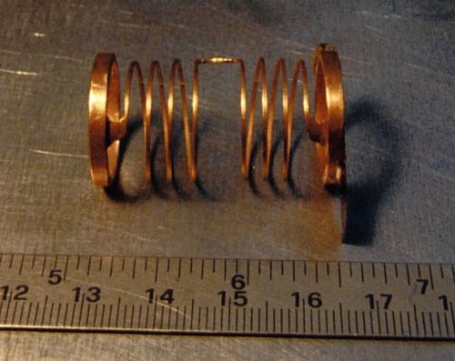
Figure 5. One of the 4 helical springs to be used for suspending the GG test bodies; two such springs are needed for each test body (see Figure 4). This spring has been manufactured in CuBe by DG Technology Service, Parma (Italy) according to our design. They have manufactured the spring by electroerosion in 3D from a single piece of CuBe with special equipment, and then have applied Brush-Wellman heat treatment and ultrasound cleaning. The elastic properties are close to the desired ones. Each spring is clamped by the thick rings at its ends. Half turns of this spring are clockwise and the other half counter- clockwise; this is for de-coupling torsional from longitudinal (axial) oscillations. No electric signal is required to pass through these helical springs.
2.4 Dissipation, whirl motions and their stabilization
The GG bodies all spin at a frequency much higher than their natural frequencies of oscillation (which are very low because of the very weak suspensions that can be used in absence of weight). This state of rotation is very close to that of ideal, unconstrained, rotors and allows the test cylinders to self-center very precisely (the center of mass of an ideal free rotor would be perfectly centered on the spin axis). However, suspensions are not perfect, which means that, as they undergo deformations at the frequency of spin, they also dissipate energy. The higher the mechanical quality of the suspensions, the smaller the energy losses. Energy dissipation causes the spin rate to decrease, hence also the spin angular momentum will decrease; and since the total angular momentum must be conserved, the suspended bodies will develop slow whirl motions one around the other. Although very slow, whirl motions must be damped. In GG they are damped actively with small capacitance sensors/actuators and appropriate control laws which have been developed, implemented and tested in a numerical simulation of the full GG satellite dynamical system using the software package DCAP of Alenia Spazio (also checked by simulating the GG dynamical system in Matlab). Simulations include drag free control as well. They demonstrate that the system can be fully controlled and that the control does not affect the expected sensitivity of the GG experiment. In fact, with the measured value of the quality factor of the suspensions (see Figure 7), whirl motions of the test cylinders are so slow that they can be damped at time intervals long enough to allow data taking in between, when active damping is switched off and will therefore produce no disturbance at all on the EP experiment.
Damping of whirl motions in the GG experiment has been the subject of extensive analysis, by the GG Science Team as well as within ESA (European Space Agency). Doubts have been expressed and a paper has been published (Jafry and Weinberger, 1998) arguing that the GG proposed test of the Equivalence Principle would be limited to a sensitivity of 1 part in 1014, which is 3 orders of magnitude worse than the sensitivity expected by the GG Team. The issue has now been settled (Nobili et al., 1998b Ch. 6; Nobili et al., 1999). The plots of Figure 8 are worth showing; although they refer to a simplified 2-body model, they show a very clear comparison between the two approaches. Results from simulations of the complete system can be found in Nobili et al., 1998b, Ch. 6. The basic physical principles which govern the behavior of weakly coupled fast spinning rotors in space may also be of interest to the reader due to the novelty of the subject (Nobili et al., 1996).
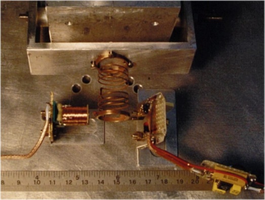
Figure 7. One helical spring to be used for suspending the GG test bodies (see Figure 5) clamped and ready for measuring its quality factor at a frequency of a few Hz. A small mass is attached to the free end of the spring in order to obtain the desired oscillation frequency. Note that the measurement is done for horizontal oscillations for the result not to be affected by local gravity. The best measured value (at 5 Hz) was 19,000.
It is clear by now that fast rotation and weak mechanical suspensions are the main features of the GG experiment design, distinguishing it from the STEP design. Other advantages of fast rotation beside the modulation of the signal are that a large number of perturbing effects (e.g. due to inhomogeneities of the test bodies, spacecraft mass anomalies, non-uniform thermal expansion, parasitic capacitances, etc.) appear as DC because the entire system is spinning. In addition, Earth tidal effects act on the test bodies at twice the spin/signal frequency.
The error budget for the GG experiment is given in the "GG Phase A Study Report" (Nobili et al., 1998b). In the worst case assumption of flying close to solar maximum (when air drag perturbation is maximum) and using values already measured in the laboratory for key quantities such as the quality factor and the common mode rejection, the experiment target of testing the Equivalence Principle to 1 part in 1017 appears to be achievable (see Table 1).
Table 1. GG error budget for a target of 1 part in 1017 in EP testing (
SI units). Worst case: launch close to solar maximum; maximum drag value along the orbit assumed. Q as measured in the lab; Common Mode Rejection as tested (taken from the "GG Phase A Study Report" (Nobili et al., 1998b)Acceleration (transverse plane) DUE TO: |
Formula |
Frequency (inertial frame) (Hz) |
Frequency (detected by spinning sensors) (Hz) |
Phase |
Differential acceleration (m/sec2) |
Differential displacement (m) |
|
w.r.t. Earth |
test body to center of Earth |
 h=520 Km |
w dm @ 1.15× 10⁻² 545 sec diff. period |
||
Air Drag |
|
|
|
~ along track |
 |
|
Solar radiation pressure |
|
 |
|
test body to center of Earth component |
same
|
|
Infrared radiation from Earth |
|
|
|
test body to center of Earth |
same
|
|
Earth coupling to test bodies quadrupole moments |
|
|
|
test body to center of Earth |
|
|
Mechanical thermal noise |
|
|
|
random |
|
|
Total Error Budget |
|
3. Preliminary Results from the "Galileo Galilei on the Ground" (GGG) Prototype
Although the GG payload designed for flight is useless at 1-g, a variant of it can be designed which can operate in the more difficult 1-g environment and also share the most important features of the space experiment: namely, that the test cylinders are weakly coupled and fast rotating and their relative displacements are detected by capacitance bridge sensors co-rotating with the test cylinders.
The GGG experiment set-up is made of two test bodies (in the shape of coaxial cylinders) in a coupled mechanical suspension (as shown in Figure 9). In between the test cylinders are placed capacitance sensors forming a bridge to measure displacements of the test cylinders relative to one another in the horizontal plane. A motor sets the whole system in rotation along a vertical axis. The laminar suspensions of the test bodies (see Figure 10) are designed to withstand the local force of gravity along the vertical while being very weak in response to any force in the horizontal plane. An EP violation would appear as a differential force between the test bodies in this plane; if the Earth is the source mass the signal is directed in the North-South direction; if the Sun is the source mass the signal will point to the Sun and therefore change during the day. In both cases it is modulated at the frequency at which the apparatus (including the capacitance sensors) is spinning. Because of the test bodies being suspended, only the small component of the gravitational force (either from the Earth or from the Sun) in the horizontal plane provides a driving signal for testing a possible violation of equivalence. This is why a space experiment is much more advantageous (by about 3 orders of magnitude!): were two apparata, one in space and the other on the ground, to have the same sensitivity in detecting the differential displacement caused by an EP violation, the apparatus in space would test the Equivalence Principle 3 orders of magnitude better than the one on the ground, simply because of the stronger driving signal. In addition, the apparatus in space would benefit substantially from the absence of weight.
Figure 9. Section through the spin axis of the GGG experiment set up inside a vacuum chamber at the laboratory of Laben in Florence. The drawing is to scale, the diameter of the vacuum chamber being 1 m. See text below for a description of all its parts.
With reference to Figure 9, the GGG system can be described as follows. It is made of 4 rotors. One is the suspension tube, held by a shaft turning inside ball bearings; rotation is transmitted from the motor (in violet on the left) to the central shaft by means of 2 O-rings. The 2 test cylinders are shown in green (the inner one) and blue (the outer one). They are suspended by means of 2 laminar suspensions (in red; see picture in Figure 10) from the top (the blue cylinder) and the bottom (the green cylinder) of a coupling arm (the fourth rotor of the system). The third laminar suspension placed at the center of the coupling arm suspends the arm itself and the entire weight from the center of the suspension tube. The suspension point of the coupling arm can be finely adjusted along the vertical; the zero position of the whole pendulum (made of the coupled system of test bodies) and the period of the differential oscillations of the two bodies of the pendulum can be finely adjusted mechanically by means of appropriate rings and screws of small mass. The capacitance plates of the read-out are shown in between the test masses (see Figure 15). The two rings (in yellow) mounted on the suspension tube contain the 2 capacitance bridges, their preamplifiers, the signal demodulators, the A/D (analog-to-digital) converters and the driver of the optical emitter, which is located at the very top of the rotating shaft (in order to transmit the demodulated signal from the rotor to the non rotating frame and then outside of the vacuum chamber). At the top of the shaft there are 2 sliding contacts for power transmission to the electronics of the rotor through a stabilized power supply (in yellow on a dish on top of the rotor). To this dish is also attached a simple optical device which provides a reference signal for the phase of the rotor. The passive damper is shown under the lowest laminar suspension and it is obviously not rotating. The two vertical screws (in light blue) allow us, by means of a chain at the top to move a platform up and down holding the test cylinders during the assembling phase. The non rotating frame and the vacuum chamber are drawn in gray.
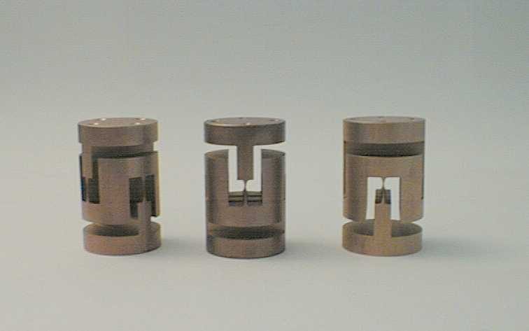
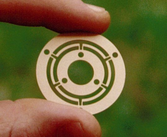
Figure 10. The three laminar suspensions of the GGG apparatus. They have been manufactured in CuBe by electroerosion in 3D following the same procedure as for the GG helical springs (see Figure 5).
Although the GGG design shown in Figure 9 may look quite complex, it can be reduced to the simple dynamical scheme of Figure 11: a balance with a vertical beam (rather than the usual horizontal one) which can be finely balanced so as to reach long differential periods of oscillation, hence a weak coupling of the test bodies. This makes them sensitive to tiny differential forces such as the one which would arise because of an EP violation. So far the system has been balanced, by adjusting the values of the masses, to D m/m = 1/200,000 reaching a differential period of about 100 sec. The spin frequency is always higher than the natural differential frequency and the system is, like in the proposed space experiment, in supercritical rotation. In such a case it is well known that the suspensions dissipate at a frequency close to the spin frequency: the higher the quality factor at this frequency, the smaller the losses in the system and correspondingly the level of thermal noise. This is a favorable situation because the quality factor is found to be higher at higher frequencies. The quality factor Q of the laminar suspensions has been measured (for horizontal oscillations at 5 Hz) with the simple apparatus shown in Figure 12. The capacitance read-out has been tested on bench; it was possible to detect 5 picometer displacements in 1 sec of integration time (with 100 pF capacitance plates). The whirl motion at the natural frequency of differential oscillation, which is known to develop in a system spinning at frequency higher than the natural one, is damped passively by providing a very small amount of non rotating damping. The first passive damper used is shown in Figure 9, at the bottom of the inner test cylinder: a 0.1 gram disk produces friction on a well polished surface as it spirals in the horizontal plane at the natural frequency. At present we have mounted a passive oil damper in which the very light disk produces non rotating damping by viscous friction in oil; although very light, it has been found to stabilize the rotor up to a spin frequency of 6 Hz and to produce less disturbances than the previous one. A simple mechanical system has been realized which allows the damper to be switched on and off. Since the whirl motion grows very slowly it is possible in this way to turn off the damper, thus avoiding any disturbances at all from it. However, viscous friction depends on the second power of the velocity at which the light disk moves in oil: as the whirl motion is damped, the velocity of the disk is reduced until a point is reached where viscous friction is no longer sufficient to further reduce the whirl radius. An active damper, made of small capacitance sensors and actuators (similar to the active damper designed for the stabilization of whirl motions in the GG experiment in space), has been designed for GGG and will be implemented soon in order to damp whirl motion even when it is very slow (i.e. small whirl radius). Tests with oil dampers using heavier disks (and also other shapes) are planned.
Figure 11. Simple dynamical scheme showing how the GGG test bodies, two hollow cylinders, are coupled. Although they are suspended so as to make them concentric (see Figures 9 and 13), they are coupled in such a way as to behave like in an ordinary balance, except for the fact that the beam of the balance is vertical and that there is a weak elastic coupling in the horizontal plane. Dynamical systems of this kind can be treated similarly to very well known models and long periods of differential oscillation can be obtained by accurately balancing the masses and their arm lengths.
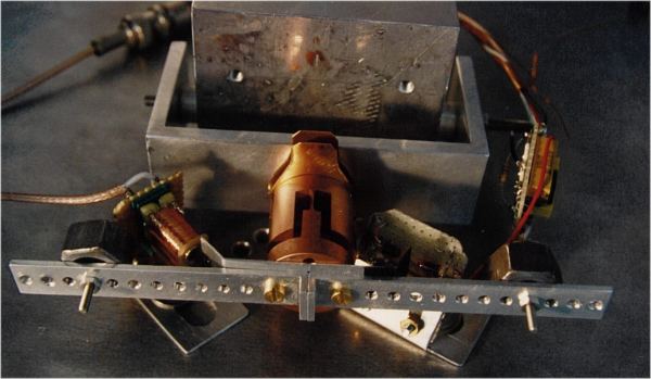
Figure 12. One of the GGG laminar suspensions clamped and mounted for Q measurement in horizontal oscillations at a few Hz. The largest value obtained was 2,000; it improved at lower amplitudes but the measurements then became limited by seismic noise. A collaboration is underway with the University of Rochester (Department of Mechanical Engineering), in order to identify materials with higher Q which could be used to manufacture the suspensions of GGG and GG.
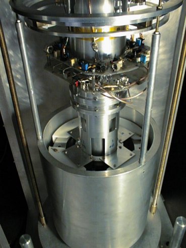
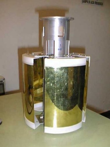
Figure 13. View from the top of the GGG test cylinders (10 kg each) one inside the other. The four capacitance plates of the read-out located in between them can be recognized (see next Figure). The electronics is visible; the coupling arm and the 3 laminar suspensions are not visible.
The GGG rotor has been assembled in the vacuum chamber and the data acquisition system has been put to work. Preliminary tests have been run with differential periods of 10¸ 15 sec and a spin frequency of 6 Hz maximum. At first we have measured the quality factor Q of the system at the natural frequency of differential oscillations; this test is performed at zero spin rate, by monitoring the decay with time of the amplitude of the oscillations of the test cylinders one with respect to the other. The passive damper was not on during the measurement. The results are shown in Figure 15. Note that when the system is rotating at a frequency higher than the differential one losses take place at the spin frequency, not at the natural one; this is a well known property of supercritical rotors. The corresponding quality factor (which is expected to be higher because of the higher frequency) can be measured by monitoring the growth in time of the amplitude of the whirl motion.
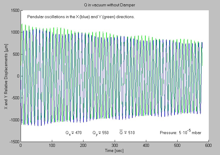
Figure 15. Measurement of Q for pendular oscillations of the GGG rotor for a differential period of oscillation of the test cylinders one with respect to the other of about 15 sec. A higher value is expected at the (higher) spin frequency, which is the relevant frequency for losses in the system when it is put into rotation (well known for rotors in supercritical rotation).
Preliminary measurement data obtained with the system in rotation are reported and commented in Figures 16 and 17. The GGG system of weakly coupled and fast spinning macroscopic rotors (10 kg each) appears to be a suitable apparatus for the measurement of small differential effects with a high frequency modulation of the signal, indicating that the physics behind its design is correct. Not being a single rotor, the alignment of the bodies is more difficult than it is for ordinary supercritical rotors; it results in a DC signal in the rotating frame, hence in a signal at the spin frequency in the non-rotating plots of the Figures below. This misalignment can be reduced.
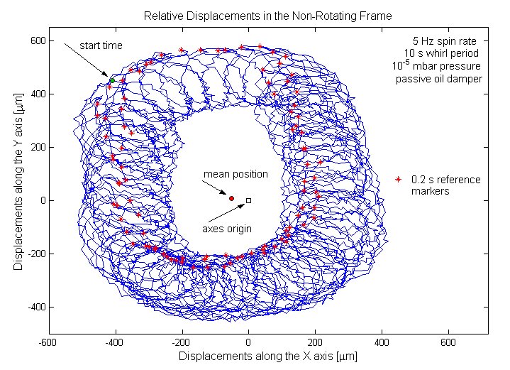
Figure 16. Relative displacements of the GGG test cylinders in the horizontal (x,y) plane (normal to the spin axis) while the whole GGG rotor is spinning at 5 Hz. By using the reference signal linked to the rotation of the system the measurement data, which are taken by the rotating capacitance sensors, have been transformed to the non-rotating frame. The large amplitude oscillations are performed with the period of whirl (10 sec) while the small (blu) oscillations have the period of spin (0.2 sec), thus indicating a misalignment in the rotor. Note that a differential effect like an EP violation should appear as a fixed displacement in this plot; the one shown in this preliminary data (given by the mean position) is still too large to be significant for EP testing.

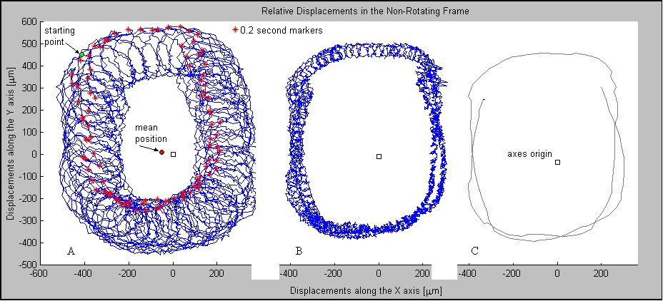
Figure 17. The same measurement data shown in Figure 16 are reported here in the A plot, to be compared with plot B where the 5 Hz signal (due to a misalignment in the rotor) has been partially filtered out using the algorithm: X(t)=(X(t)+X(t+0.1 sec))/2 and Y(t)=(Y(t)+Y(t+0.1 sec))/2 (note that 0.1 sec is half the spin period). Finally, in plot C the 5 Hz signal has been completely filtered out by averaging the X and Y data in groups of 0.2 sec leaving only the whirl motion. The remaining "bumps" are defects in the data acquisition system (hardware and/or software) which need to be corrected.
The passive oil damper discussed in the previous Section is very effective in damping large whirl motions and ensuring stable rotation at high spin frequencies; so far we have reached 6 Hz, which is quite high for bodies of 10 kg coupled by a low stiffness elastic constant. However, it is not capable (in its present configuration) to damp whirl motions of small radius (hence slow velocity), thus leaving a rather large signal at the natural frequency of differential oscillations (as shown in Figures 16 and 17). A finer active damper (with small capacitance sensors and actuators as envisaged for GG) is in preparation. Then we know there are several physical effects to be taken care of before a significant EP test can be carried out with this apparatus: seismic noise, gyroscopic effects, Earth tidal effects. We have investigated these effects, both analytically and with numerical simulations (see Comandi, 1999); testing the Equivalence Principle to a level competitive with the torsion balance is not easy, but we are confident that it is possible. Over the torsion balance it would have the major advantage of being the prototype of an apparatus which can be flown in space, where lies the only realistic hope to achieve a very high accuracy test of the Equivalence Principle.
The GG space project has been funded from its start by the Italian Space Agency (ASI). Funding for the GGG ground experiment has been recently approved by the Italian National Ministry of University and Scientific and Technological Research (MURST), as well as by the University of Pisa. Laben has provided continuous support by hosting the GGG experiment in its laboratories in Florence. We wish to express our thanks to all of them. In addition, thanks are due to those colleagues who have supported our efforts to re-establish the physical bases of the GG design against groundless claims; the warmest thanks go to Professor Stephen H Crandall (MIT, Department of Mechanical Engineering, Cambridge, USA).
Blaser, J.P., M. Bye, G. Cavallo, T. Damour, T., C.W.F. Everitt, A. Hedin, R.W. Hellings, Y. Jafry, R. Laurance, M. Lee, A.M. Nobili, H.J. Paik, R. Reinhard, R. Rummel, M.C.W. Sandford, C. Speake, L. Spencer, P. Swanson, and P.W. Worden Jr., "Satellite Test of the Equivalence Principle", Report on the Phase A Study, ESA/NASA SCI (93)4 (1993)
Blaser, J.P., Cornelisse, J., Cruise, T. Damour, F. Hechler, M. Hechler, Y. Jafry, B. Kent, N. Lockerbie, H.J. Pik, A. Ravex, R. Reinhard, R. Rummel, C. Speake, T. Sumner, P. Touboul and S. Vitale, STEP: "Satellite Test of the Equivalence Principle", Report on the Phase A Study, ESA SCI (96)5 (1996)
Braginsky, V.B., V.I. Panov, "Verification of the Equivalence of Inertial and Gravitational Mass", Sov. Phys. JEPT, Vol. 34, pp. 463-466 (1972)
Comandi, G. Laurea Thesis in Physics, University of Pisa, (1999). Available online: http://tycho.dm.unipi.it/nobili/theses/comandi.html
Eötvös, R.V., D. Pekar, E. Fekete, "Beitrage zum gesetze der proportionalität von trägheit und gravität", Ann. Physik, Vol. 68, pp. 11-66 (1922)
Jafry Y and M. Weinberger, "Evaluation of a Proposed Test of the Weak Equivalence Principle Using Earth-Orbiting Bodies in High-Speed Co-Rotation", Class. Quantum Grav. 15 481-500 (1998)
Nobili, A.M., D. Bramanti, E. Polacco, G. Catastini, A. Milani, L. Anselmo, M. Andrenucci, S. Marcuccio, G. Genta, C. Delprete, E. Brusa, D. Bassani, G. Vannaroni, M. Dobrowolny, E. Melchioni, C. Arduini, U. Ponzi, G. Laneve, D. Mortari, M. Parisse, F. Curti, F. Cabiati, E. Rossi, A. Sosso, G. Zago, S. Monaco, G. Gori Giorgi, S. Battilotti, L. D'Antonio and G. Amicucci, "GALILEO GALILEI. Flight Experiment on the Equivalence Principle with Field Emission Electric Propulsion", J. Astronaut. Sc., 43, 219-242 (1995)
Nobili, A.M., D. Bramanti, G. Catastini, A. Anselmi, S. Portigliotti, A. Lenti, G. Volpi, S. Marcuccio: "GG-Experience en vol sur le principe d'equivalence avec propulsion electric par emission de champ; GALILEO GALILEI (GG)-Test of the Equivalence Principle with a Small Spinning Spacecraft: The Stabilization of its Weakly Coupled Masses", in Scientific Satellites Achievements and Prospects in Europe", Proceedings, AAAF-ESA, 3-74/89, (1996). Available online: http://tycho.dm.unipi.it/nobili/ggweb/referenze/aaaf.pdf
Nobili, A.M., D, Bramanti, E. Polacco, G. Catastini, G. Genta, E. Brusa, V.B. Mitrofanov, A. Bernard, P. Touboul, A.J. Cook, J. Hough, I.W. Roxburgh, A. Polnarev, W. Flury, F. Barlier, C. Marchal, "Proposed Non Cryogenic, Non Drag Free Test of the Equivalence Principle in Space", New Astronomy, 3, No. 3, pp. 175-218 (1998a). Available online: http://pigeon.elsevier.nl/journals/newast/jnl/by-vol-issue.html#3_3 http://tycho.dm.unipi.it/nobili/ggweb/newastronomy/paper/Menu.html
Nobili et al (with the GG Science Team), Galileo Galilei (GG): Phase A Study Report, ASI (1998b). Available online: http://tycho.dm.unipi.it/nobili/ggweb/phaseA
Nobili, A.M., D. Bramanti, E. Polacco, G. Catastini, A. Anselmi, S. Portigliotti, A. Lenti, P Di Giamberardino, S Monaco, R Ronchini: "Evaluation of a Proposed Test of the Weak Equivalence Principle Using Earth-Orbiting Bodies in High-Speed Co-Rotation: Re-Establishing the Physical Bases", Class. Quantum Gravity, 16, 1463-1470 (1999). Available online: http://www.iop.org and http://tycho.dm.unipi.it/nobili/evaluation
Roll, P.G., R. Krotkov, R.H. Dicke, "The Equivalence of Inertial and Passive Gravitational Mass", Ann. Phys., N.Y., Vol. 26, pp. 442-517 (1964)
Su, Y., B.R. Heckel, E.G. Adelberger, J.H. Gundlach, M. Harris, G.L. Smith and H.E. Swanson, "New tests of the universality of free fall", Phys. Rev. D, Vol. 50, pp. 3614-3636 (1994)
Worden, Jr., P.W. and C,W.F. Everitt, "Test of the Equivalence of Gravitational and Inertial Mass Based on Cryogenic Techniques", in Proc. Int. School of Physics E. Fermi, Course LVI: Experimental Gravitation, Academic Press, New York, pp. 381 (1973)
Worden, Jr P.W., "A Cryogenic Test of the Equivalence Principle", PhD thesis, Stanford University, Stanford, California, (1976)
Worden, Jr., P.W., Acta Astronautica, 5, 27 (1987)

