5 The GG Satellite
5.1 Launch Requirements and Constraints
5.2 Satellite Configuration
5.3 Mechanical Design
5.3.1 Structural Design
5.3.2 Launcher Mechanical Requirements
5.3.3 Materials Selection And Properties
5.3.4 Structural Mass Budget
5.3.5 Finite Element Model and Structural Analysis
5.4 Spacecraft Thermal Control
5.4.1 Thermal Control Subsystem (TCS) Requirements
5.4.2 TCS Concept And Configuration
5.4.3 TCS Performance
5.4.4 Conclusions and Critical Areas
5.5 Spacecraft Attitude Control
5.6 On Board Data Handling
5.7 Tracking, Telemetry and Command
5.8 Power Supply
5.9 Satellite Budgets
This chapter ready to download and print (0.5 MB): chapter5.pdf
Candidate Launch Vehicles. The requirements call for a low-cost launch vehicle able to inject up to 263 kg into low, circular, equatorial orbit. Furthermore, to simplify the early orbit operations, an ability to deploy the satellite in a spinning mode, with the spin axis approximately perpendicular to the orbit plane, is sought.
A number of 'small' launch vehicles, potentially meeting the above requirements, is either available or in an advanced development stage. As well as providing the mass and fairing envelope size required by GG, a candidate launcher must demonstrate the ability to launch into equatorial orbit, either directly (i.e., from an equatorial launch site) or by a delta-inclination manoeuvre. Based on these criteria, three candidates have been identified as suitable:
Pegasus was the best documented launcher at the time the work on which this report is based was performed (1998). Moreover, its characteristics (failing envelope, limit loads, payload mass) are by far the most constraining of the three. For these reasons, our design exercise was focused on Pegasus. Table 5.1 (ref. OSC Pegasusâ Users' Guide, Release 4.0, September 1998) shows the characteristics taken as the basis of the exercise. To further ensure compatibility across the range of the three vehicles, increased margins were taken in the design, particularly for the normal modes at launch.
Type: |
Pegasus XL |
Launch site: |
Alcantara, Kwajalein (provided as a non-standard service) |
Mass into orbit: |
» 380 kg (520 km circular, equatorial) » 370 kg (600 km circular, equatorial) |
Payload dynamic envelope: |
diameter 1168.4 mm (46"), height 2138.7 mm (84.2") (without HAPS) height 1767.8 mm (69.6") (with HAPS) (HAPS = Hydrazine Auxiliary Propulsion System) |
Standard adapter interface diameter: |
590.5 mm (23") |
Separation system (remaining with the S/C) mass: |
@ 3.95 kg |
Design limit loads & dynamic requirements: |
see paragraph 5.3.1 |
Table 5.1 Pegasus Launch Vehicle Characteristics
The PSLV is designed for launch of 1000-kg class spacecraft into sun-synchronous orbits from a launch site at 13.9º latitude. A number of qualification flights have been performed and the launcher is now operational. The fairing envelope and required interfaces are amply compatible with GG. GG requires a 90º launch azimuth (to reach an inclination close 14º) and a final dog-leg manoeuvre (to move the satellite into an equatorial orbit). Analytical investigations show that the first three stages of the vehicle are sufficient for placing GG into 520 km circular orbit, leaving the fourth stage for the delta-inclination manoeuvre. The 90º launch azimuth does not seem to be precluded by geographical constraints (the launch site lies at the SHAR Center in Sriharikota, on the East Indian coast at 13.9° N).
Should the European small launcher VEGA be available at the time of the GG mission, it would be the prime choice. The dimensions of the launcher fairing (2 m in diameter and 3.5 m in height) are far more ample than those considered in this report’s design exercise. The VEGA launch mass capability for the reference orbit (from Kourou) is better than required, with over 1000 kg in the K3 version. A launcher to S/C standard interface of 937 mm (TBC) is foreseen; if that is confirmed, then a suitable adapter must be designed for GG.
Orbit Injection Performance. As a baseline, no capability for correction of injection errors will be available on board GG. The residual eccentricity is typically not larger than 0.01, which is acceptable for GG. Based on User Manual information, the injection performance of PSLV and VEGA meets this requirement. Pegasus would require use of its hydrazine auxiliary propulsion system (HAPS), which is anyway a standard feature offered by the launcher. We conclude that precise orbit injection as required by GG can be reached by all candidate launchers.
Attitude orientation at separation: All the launcher upper stages provide a spin and pre-defined orientation of the spin axis before separation. For a typical case, we consider Pegasus. Spin up to 16.7 rpm (0.28 Hz) is nominally provided, while rates above 16.7 rpm are considered a non-standard service and depend on the amount of propellant left. Therefore, an autonomous system for spin-up to the required 120 rpm must be provided by the satellite.
The typical pre-separation performance is as follows:
Given these errors, the autonomous spin-up system mentioned above must also provide for correction of angular momentum depointing and damping of angular rates. The reaction control system of GG has been sized for the above requirements (worst-case, as they come from the most demanding of the three candidate launchers). Note that a precise value of the nominal spin rate of the GG spacecraft is of no importance for the scientific goal of the mission.
The main configuration requirements are:
The above requirements cannot be reconciled with a structural configuration derived from the PRIMA bus. Therefore, a configuration built around the payload module (PGB) was preferred as shown in Fig. 5.3.
The structure (see Fig. 5.1 and Fig. 5.2 where the solar panels have been removed for clarity) is made up of a central cylinder and an upper and lower truncated cone. The upper cone is removable to allow the integration of the PGB with its suspension springs; the lower cone supports the launcher interface ring. The equipment are mounted on the central cylinder by means of suitable cut-outs, and to the upper and lower cone. The solar panel is divided into two pieces to make room for the equipment mounted in the central belt, including thrusters and sensors (Fig. 5.3); this solution also allows a suitable distribution of thermal covers and radiators to realise an efficient thermal control. The total height of the satellite (antennas not included) is
1.31 m; 0.93 m in eight is allocated to the solar arrays allowing for sufficient power output. The mass distribution permits to reach a value of b » 0.3.
Figure 5.1 Structural configuration (side view) with solar arrays removed. The structure, completely enclosing the PGB laboratory (shown in outline), is made up of three parts: (a) central cylinder with 1 m diameter, providing cut-outs for the equipment accommodated outboards for reasons of field of view or thermal dissipation; (b) upper truncated cone, with the interface to the PGB suspension system, and (c) lower cone, symmetrically placed, hosting the launcher interface ring. (All distances in the drawing are in mm).
Figure 5.2 Structural configuration (3D view) with solar arrays removed. This 3D view shows the accommodation of the equipment on the upper and lower cones as well as in the central cylinder, and the S-band antennas. This compact configuration results in a very stiff structure, with high frequency margins with respect to the launcher requirements.
Figure 5.3 External configuration with solar panels and antennas. The picture on the left shows the stowed bottom antenna (launch configuration), and the picture on the right the deployed position. No deployment mechanism is needed for the top antenna.
The final configuration comprises, from bottom to top, the following items:
- a
23" (0.584 m) interface ring with the launcher;The station of the equipment ring w.r.t. the PGB can be adjusted (thanks to the sufficient gap between the PGB and the structure in the spin axis direction), such that the centre of mass of the satellite is placed in the mid-plane of the figure of revolution (an important consideration for minimizing the torques due to surface forces).
Fig. 5.4 shows the configuration under the Pegasus fairing and Figs. 5.5a/b show the equipment configuration in the central cylinder and the layout of the FEEP thrusters in the equatorial region.
Figure 5.4 Configuration under the Pegasus fairing
|
|
(a) |
(b) |
Figure 5.5 (left panel (a)) Equipment
location in the central cylinder. The equipment include the Power Protection and
Distribution Unit (PPDU), Coarse Sun Sensor (CSS), the spacecraft control system
electronics (ICS), the transponder, the battery and the Earth and fine sun sensor box ;
the clearance with respect to the PGB is shown too. ;
(right panel (b)) Configuration of the FEEP thrusters. Six
thrusters are used, placed in two groups of three on opposites sides of the spacecraft
according to the scheme described in chapter 5.5. Each thruster package carries its own
small propellant reservoir, dispensing with tanks and feed lines. Each cluster of three
thrusters is served by an electronic package mounted close to it.
Launch Locking of the PGB Assembly For launch-locking of the PGB assembly to the structure (to transfer the inertial launch loads), two concepts have been elaborated. In the first option, the locking mechanism is placed on the area housing the suspension spring device; then, the launch loads use the circular lower platform to reach the launcher interface
In the alternative concept illustrated in Fig 5.6, a short cylinder is used to mount a lock/unlock mechanism composed by three pins, equally spaced along the circumference. Such mechanism would be actuated by means of a set of springs (to move the pins in the unlocked position), tensioned wires (to actuate the pins locking against springs) and electrically actuated cutters (acting on the wires). The advantages of this solution are that (a) the load path is shorter, reducing the PGB bounce response, and (b) the lock device is moved away from the area of the suspension springs device, reducing its complexity. A trade-off between the two solutions will be performed in the detailed design phase. Whatever the final choice for this lock/unlock device, a set of 8 inch-worms (4 at the top and 4 at the bottom), will be placed between the PGB central tube and a short spacecraft tube for a finer, controlled, release of the PGB. The inch-worms are arranged at 90º from one another, in between the active dampers as shown in Fig. 2.20; the unlocking procedure is discussed in Sec.2.1.6. In addition, the PGB has mechanical stops in all similar to those of the test bodies with radial shafts being allowed only very limited movements (about half a cm); see Sec. 4.1 and Fig. 4.3.
Figure 5.6 Alternative lock/unlock mechanism concept
Mass Compensation System Thermal distortion of the spacecraft structure will change the moment of inertia about the spin axis, hence, at constant angular momentum, the spin rate (see Sec. 2.1.2). The effect can be compensated for by suitable masses suspended on rods that expand and contract in "counterphase" to the spacecraft. The system can consist of a high-CTE rod cantilevered (and thermally anchored) on the outer shell and connected to a parallel, low-CTE rod supporting a balance mass on its free end (Fig. 5.7a). However, configuration constraints lead to short rod lengths and large balance masses. Moreover, the large spin centrifugal force suggests to modify the scheme into that of Fig. 5.7b. Yet another concept is based on two rods in a triangular configuration supporting the balance mass (Fig. 5.7c). Angle
a is constrained by considerations of friction angle and linearity. In a preliminary sizing, the rod's Dl is amplified by a factor of @ 1/sina @ 6, allowing use of conventional Al alloy rods and small balance masses, on 4 positions around the cylinder. Solution (c) was adopted for the purposes of the mass budget in Table 5.18.
Figure 5.7 Concepts for the passive compensation of thermal expansion and contraction
The task of the structure is to support the satellite equipment through all mission phases including transportation; the structure is conventionally divided into a "primary structure", to withstand the launch loads and a "secondary structure" composed of brackets and other minor attachment points. The structure provides the following functions:
- it supports all the spacecraft (S/C) equipment
- it transfers the launch loads to the launcher interface
- it has adequate stiffness to decouple S/C to launcher modes
- it guarantees alignment between critical equipment
- it contains equipment mounting brackets (if necessary)
- it allows for ballast mass(es) allocation due to balancing needs (if any) of the overall
integrated spacecraft
- it allows for thermal decoupling
- it gives support to passive thermal protection (e.g. MLI)
- it gives support to thrusters and plumbing
- it gives equipment protection against launch vehicle vibration environment
- it allows electrical ground return service as part of the electrical distribution system
- it minimises electrostatic discharge problems
- it has dedicated points (and/or areas) for S/C lifting and suitable interface(s) toward
the launch vehicle.
The GG satellite is mainly composed of:
- the PGB package
- the primary structure surrounding the PGB
- the solar panels.
The PGB is connected via suitable suspension springs (locked at launch) to the primary structure; the latter interfaces the launcher separation plane via a standard (Pegasus 23") adapter ring.
5.3.2
Launcher Mechanical Requirements
The satellite structure has been designed to be compatible with the PEGASUS launcher environment. Preliminary data about the VEGA launcher have been included for comparison. The study has been performed using the requirements coming from the PEGASUS launcher; they are:
-frequency requirements
-dimensioning loads
-safety factors
-S/C Centre Of Mass location
Frequency Requirements. To avoid dynamic coupling between the launcher low frequency modes and the spacecraft modes, the spacecraft shall be designed with adequate structural stiffness. The minimum eigenfrequency requested to the spacecraft in hard-mounted condition at the separation plane is 20 Hz (i.e. excluding the S/C separation system). In order to take into account the uncertainties connected to the study maturity, we set for the preliminary structural design a value > 40 Hz.
The VEGA launcher minimum eigenfrequencies at launch are 18 Hz (TBC) in lateral and 30 Hz (TBC) in axial mode, hence largely met by our 40 Hz design target.
Dimensioning Loads. The S/C primary structure shall be sized under the most severe combination of loads that can be encountered at any given instant of flight assuming the lateral loads may act in any direction simultaneously with longitudinal loads. The design limit loads to be used in the static analysis are shown in Table 5.2; they refer at the base of the separation system.
The VEGA launcher Quasi Static Loads at launch are
±1.0 g’s (TBC) in lateral and –8.0 g’s (TBC) in axial direction w.r.t. the launcher body.|
|
Axial (g's) |
( *) |
Lateral (g's) |
|||
| Static |
Dynamic |
Total |
Static |
Dynamic |
Total |
|
Taxi, Abort and Captive Flight |
±1.0 |
N/A |
±1.0 |
3.67 |
N/A |
3.67 |
Aerodynamic Pull-Up |
-3.7 |
±1.0 |
-4.7 |
2.34 |
1.41 |
3.75 |
Stage Burn-out (**) |
-9.2 |
±1.0 |
-10.2 |
0.28 |
1.41 |
1.69 |
Note: (*) the minus sign (associated to the S/C
"Z" axis) indicates compression
(**) the static
value depends on the "Payload" mass here assumed to be 300 kg.
Safety Factors. Pegasus launcher requires different Safety Factors depending on the design and test options. A value of 1.5 and 1.1 at ultimate and yield respectively is demanded if the "proof test on each flight article" is chosen; an ultimate Safety Factor of
3.0 has been assumed for unconventional materials (e.g. CFRP).No data are yet available about the VEGA launcher safety factors; use of standard values is hence recommended.
S/C Centre Of Mass location. Pegasus launcher limits the S/C centre of mass location as follows:
The proposed configuration is in agreement with the above data.
5.3.3 Materials Selection And Properties Drivers in the structural materials selection have been the strength capability, the stress corrosion resistance and CTE values for those parts which must insure high mechanical stability. The used materials are:- 7075 Al-alloy
- CFRP (for sandwich skins).
A trade-off has been performed between Al-alloy and CFRP materials for honeycomb skins; mass over stiffness ratio is nearly the same for the two classes of materials, hence the CFRP material has been chosen as baseline in order to reduce as much as possible the S/C thermal distortion.
The main engineering constants of the selected materials are reported in Table 5.3. The mechanical properties of the main S/C structural components (Sandwich Plates) are collected in Table 5.4.
7075-T6 Al-alloy |
|
| density elastic modulus Poisson coefficient Tensile strength (yield) Compressive strength (yield) Ultimate Shear Strength Coefficient of Thermal Expansion |
r = 2795 kg/m3 E = 71 Gpa n = 0.33 s ty = 413.7 MPa s cy = 420.6 Mpa s su = 289.5 MPa CTE = 23·10-6 m/m/°C |
Sandwich honeycomb (3/16-5052-.001 Al-alloy type) |
|
| density shear modulus L direction shear modulus W direction |
r = 49.69 kg/m3 = 310.3 Mpa = 151.7 MPa |
CFRP laminate sandwich sheets (M40/914c tape) |
|
| laminate lay-up laminate type ply thickness number of plies density E1 = E2 n 12 = n 21 s u CTE1 = CTE2 |
67% at ± 60°, 33% at 0° symmetric, quasi-isotropic 125 m m (each) 12 r = 2100 kg/m3 69.1 Gpa 0.3109 200 MPa 0.96·10-6 m/m/°C |
Upper circ. plate |
Upper trunc. cone |
Central cylinder |
Lower trunc. cone |
Lower circ. plate |
|
Honeycomb height |
0.050 m |
0.020 m |
0.020 m |
0.020 m |
0.050 m |
Honeycomb type |
3/16-5052-.001 |
3/16-5052-.001 |
3/16-5052-.001 |
3/16-5052-.001 |
3/16-5052-.001 |
Face sheets thickness |
0.00075 m (each) |
0.00075 m (each) |
0.00075 m (each) |
0.00075 m (each) |
0.00075 m (each) |
Face sheets material |
CFRP Tape M40/914c |
CFRP Tape M40/914c |
CFRP Tape M40/914c |
CFRP Tape M40/914c |
CFRP Tape M40/914c |
Table 5.5 shows the structural mass breakdown for the baseline configuration (CFRP sandwich skins). On all the structural items, both subsystem margins (+20%) and system margins (+20%) have been applied because of the low design maturity.
| Item |
Mass [kg] |
S/S Margin [kg] |
Total mass [kg] |
| Upper Platform | 1.14 |
0.23 |
1.37 |
| Upper Cone | 3.08 |
0.62 |
3.70 |
| Outermost Cylinder | 4.67 |
0.93 |
5.60 |
| Lower Cone | 3.08 |
0.62 |
3.70 |
| Lower Platform | 1.14 |
0.23 |
1.37 |
| Cones to Cylinder I/F rings (quantity = 2) | 18.46 |
3.69 |
22.15 |
| Cones to Platforms I/F rings (quantity = 2) | 7.76 |
1.55 |
9.31 |
| Lock/unlock mechanism | 2.50 |
0.50 |
3.00 |
| Separation system ring | 3.95 |
0.79 |
4.74 |
| Hardware (Inserts, cleats etc.) | 2.00 |
0.40 |
2.40 |
| Total Structure | 57.34 |
||
| System margin (20%) | 11.47 |
||
| Grand Total Structure | 68.81 |
||
The FEM model has been assembled in order to dynamically verify the compatibility of the satellite with the launcher dynamic requirements. The output in the launch hard-mounted condition consists of the eigenvalues and the eigenvectors.
The model mesh has been obtained using the SDRC I-DEAS Master Series 2.1 pre-processor software while the MSC/NASTRAN version 68.2 program has been used to solve the mathematical model; Fig. 5.8 shows the FEM mesh.
The masses represented in the FEM model(s) include both system (20% constant) and sub-system (variable depending on the sub-system considered) contingencies; the non-structural masses, i.e. equipment masses, have been concentrated in the location of the centre of mass of each equipment item, according to the chosen layout. The masses in the FEM Model include the contingencies. The FEM model used for launch analyses is fully constrained (6 DOF's) at the spacecraft to launcher interface nodes.
Static Analysis. According to usual rules in S/C mechanical design, the GG structure has been sized against stiffness; later on a static verification should be planned in order to detail the stresses in all structural elements. In this project phase, only a preliminary verification of the sandwich panels local instabilities and of the solar cells glue capability to withstand the centrifugal forces
(8.37 g's) has been performed. It is useful, anyway, to point out that (with the data we have) the dimensioning launch loads of the PEGASUS launcher encompass those of the VEGA one.Local Panel Instabilities. Sandwich structures must be designed not only to have sufficient safety factors with respect to dimensioning loads but also against local instabilities such as:
-shear crimping: the core should be thick enough and have sufficient shear
modulus to prevent overall buckling of the sandwich under load
-intracell dimpling: the core cells should be small enough to prevent the facings to
buckle or dimple into the spaces between core walls
-face wrinkling: compressive modulus of the core and compressive modulus of the facings
should be sufficient to prevent the facings to buckle as a plate on an elastic foundation.
The output demonstrated positive safety factors greater than unity for all the main components.
Solar Cell Behaviour Under Centrifugal Forces. Due to the fast rotational motion of the satellite, the solar panels, that are located at the periphery, are subject to severe centrifugal loadsFc = m·w s²·r
F× Sp = Rp /s p » 100
Normal Mode Analysis at Launch. Normal modes analysis (ref. MSC/NASTRAN Dynamic Handbook) of the S/C in hard-mounted condition has been performed and the results are reported in Table 5.6. Fig. 5.8 shows the FEM model mesh and Figs. 5.9 to 5.11 show the eigenvector plots of the first three modes. The requirement in terms of minimum "constrained" eigenfrequencies has been met; the obtained values contain however a positive margin on the minimum eigenfrequencies such to take into account the flexibility added by connection elements (e.g. cleats) and model assumptions. From the VEGA launcher viewpoint, we can stress the fact that with the assumed requirements (i.e.
f0 > 40 Hz) and the FEM output, no particular problems can now be envisaged in case the VEGA launcher were to be chosen.| Mode No. |
Frequency [Hz] |
Type |
1 |
49.3 |
Axial mode (PGB + Platforms) |
2 |
65.9 |
Lateral mode (whole primary structure) |
3 |
66.1 |
Lateral mode (whole primary structure) |
4 |
150.4 |
Local mode (PPDU) |
5 |
157.1 |
Local mode |
6 |
166.9 |
Local mode |
Figure 5.8 Finite Element Model Mesh. The final spacecraft FEM model consists of about 500 nodes and 500 elements.
Figure 5.9 Eigenvector Plot : First Axial Mode. The mode represents a ‘bouncing’ along the longitudinal symmetry axis of the whole structure, while fixed at the separation plane.
Figure 5.10 Eigenvector Plot : First Lateral Mode. The mode consists in a lateral motion of the structure, that behaves as a cantilevered boom while fixed at the separation plane.
Figure 5.11 Eigenvector Plot : Second Lateral Mode. Like the first lateral mode, it consists in a lateral motion of the structure, that behaves as a cantilevered boom while fixed at the separation plane.
Solar Panel Mechanical Characteristics. Solar panels can have either an Al-alloy or CFRP sub-structure; the following preliminary characteristics have been used:Panel flexural rigidity (Al-alloy type)[D] = 6750N·m
Panel flexural rigidity (CFRP type)[D] = 13400N·m
(see HEXCEL® TSB124 catalogue). The global solar panel mass per unit surface is 4.65 kg/m2 for the Al-alloy type and 3.45 kg/m2 for the CFRP type (nominal values without contingencies). The dynamic analysis results are pertinent to a solar panel having a CFRP sub-structure, and including mass margins.
Because of the preliminary phase of the project, no stress evaluation has been carried out for the solar panel sub-structure; we recommend to study this particular aspect in the detailed design phase.
5.4 Spacecraft Thermal Control
5.4.1 Thermal Control Subsystem (TCS) Requirements The S/C thermal control subsystem shall maintain all equipment within the temperature range applicable to their operating status in all mission phases. It shall be designed to guarantee adequate margins between the predicted units extreme temperature ranges (based on worst design cases) and the required operational temperature limits.Radiative and conductive thermal decoupling between the spacecraft and the PGB shall be implemented to minimise mutual interaction and perturbations.
For the spacecraft equipment, commonly accepted temperature limits have been assumed, as shown in Table 5.7.
| ITEM |
Operating range [° C] |
Design range [° C] |
Non-Operative range [° C] |
Design Range [° C] |
Electronic Units Batteries |
-10 to +50 0 to +20 |
0 to +40 +5 to +15 |
-20 to +60 -5 to +25 |
-10 to +50 0 to +20 |
Table 5.7
Temperature Requirements 5.4.2 TCS Concept And Configuration The main features of the S/C thermal control subsystem are shown in Fig. 5.12. The following characteristics of the thermal hardware are foreseen. MLI Blankets. MLI Blankets on external surfaces will consist of 20 layers double aluminised Kapton or Mylar with Dacron net as spacer. In the S/C parts exposed to high heat input, e.g., thruster plumes, the shield material will be 0.3 mil aluminised Kapton. The external MLI has an outer layer of 2 mil Kapton that is coated with a suitable finish.The MLI will cover all the external surfaces except the radiators and part of the FEEP's external surfaces. Furthermore internal MLI blankets will wrap units surfaces not facing the radiators with an outer aluminised foil to decouple them from the interior of the S/C and all the external PGB surface.
MLI blankets of ten layers, white painted on the side facing space will cover the back of the solar panels as well as their supports. Table 5.8 below shows the specific conductivity of the blankets introduced in the model.
| Average T [ ºC] |
-100 |
-50 |
0 |
50 |
100 |
K MLI 10 layers [W/m²] |
0.025 |
0.037 |
0.050 |
0.065 |
0.083 |
K MLI 20 layers [W/m²] |
0.017 |
0.025 |
0.035 |
0.048 |
0.062 |
 Figure
5.12 Thermal Design Concept
Figure
5.12 Thermal Design Concept
Surface Finishes. The thermo-optical properties of the surface finishes are summarized in Table 5.9 below.
| Thermo-optical Properties |
a /e Beginning of life |
a /e End of life |
| MLI I.T.O Kapton |
0.3/0.77 |
0.43/0.77 |
O.S.R Optical Solar Reflector |
0.1/0.80 |
0.15/0.8 |
5 mil Teflon G401500 |
0.09/0.75 |
0.2/0.75 |
Internal MLI |
n.a./0.05 |
n.a./0.05 |
Adapter |
0.5/0.8 |
0.5/0.8 |
Solar Array Cell Side |
0.75/0.82 |
0.75/0.82 |
Solar Array Back |
0.51/0.71 |
0.51/0.71 |
Coatings on Radiators. Considering the direct exposure to the Sun of the radiative areas, Optical Solar Reflectors (OSR’s) have been selected as baseline radiator coating to minimise the parasitic heat absorption. They require flat surfaces to be mounted, therefore flat radiators panels have been foreseen mounted on the units base plates according to Fig. 5.12. For the FEEP electronics mounted on the outside, part of their surface will operate as radiator covered by Teflon tape.
5.4.3 TCS Performance Selection of the design cases. The selection of the design reference cases is based on the following aspects:Location of the radiative surface
Mission phase and corresponding orbital data
Dissipation levels and their distribution in the S/C and in time
Attitude of the S/C
Solar aspect angle w.r.t. the radiator surfaces
Occurrence of eclipses
View to Earth.
Only the operational phase of the mission was considered: circular equatorial orbit at 520 km altitude, S/C attitude with the spin axis (2 Hz) normal to the orbital plane. Owing to the requirements on inertia moments of the S/C, the location of the equipment must be distributed as far as possible in the central belt of the satellite. This leads to have radiator surfaces directly exposed to the Sun during sunlight, consequently the hot case (sizing case for the radiators) occurs when the Sun is perpendicular to these surfaces and the albedo and infrared input are at their maximum (thermo-optical properties of surface at end of life). Conversely, the cold case (sizing case for heater power) occurs at Summer Solstice, minimum of the solar constant, albedo and infrared input (thermo-optical properties at beginning of life). The adopted constants for the hot and cold case are in Table 5.10.
Design Case
Solar Constant [W/m²]
Albedo Coefficient
Planet Flux
[W/m²]
Hot Case
1381
0.35
271
Cold case
1327
0.20
235
Table 5.10
Design casesThe data above are the input for the calculation of the external heat fluxes, performed by the THERMICA package. The spin has been taken into account by averaging the heat input over 10 spin positions. The fluxes are the external heat input for the Thermal Mathematical Model, built by means of the ESATAN package.
Results from the Thermal Mathematical Model. A transient analysis was performed; to avoid very long runs, due to a very small integration step, the MLI capacity was set to zero and only that of the structural items, equipment and Test Masses was introduced in the model (a conservative assumption).
The analyses were carried out over several orbits (more than 20) to simulate the long term behaviour of the S/C. The equipment dissipation values (Table 5.11) were introduced under consideration of the different operating modes during eclipses or sunlight phases. Concerning the battery, three different levels were considered corresponding respectively to trickle charge, overcharge and discharge periods, but the values (not available in this project phase) have been roughly estimated and should be reviewed in the next phases. To take into account of uncertainties of the equipment dissipation levels, a margin of 20% w.r.t those presented below was applied in the model in the hot case simulation, while in the cold case, performed to evaluate the heater power need, no margin was applied. The calculated heater power need is of 10 W applied on the battery during the orbit except the overcharge period.
All the equipment are maintained in the required ranges with the assumed design. Equipment box temperatures are kept around 20° C in the hot case and around 5° C in the cold case, with excursions at orbit frequency of about ± 3° C.
A preliminary mass budget of the Thermal Control equipment is shown in Table 5.12.
5.4.4 Conclusions and Critical AreasEquipment dissipation
FUNCTION
Boxes
Unit Mass
[Kg]
Unit Power Sunlight [W]
Power
Eclipse [W]
AOCS
Earth Sensor
CSS
FEEP
1.68
0.28
2.50
1.0
8.0
1.0
8.0
OBDH
ICS
7.80
12.0
12.0
POWER
Ni-Cd Battery
PPDU
5.00
8.40
1.3 trickle
8.1 overcharge
11.0
4.7 discharge
7.0
TT&C
Transponder
5.00
7.7
6.0
PAYLOAD
PGB Electronics
9.00
6.0
6.0
Table 5.12 TCS Mass budget
ITEM
Quantity [m²]
Unit mass
Total Mass [Kg]
O.S.R. 0.32
0.78 [Kg/m²]
0.249
MLI 20 layers External 2.49
0.60 [Kg/m²]
1.494
MLI 20 layers Internal 3.89
0.60 [Kg/m²]
2.334
MLI 20 layers Equipment 0.80
0.60 [Kg/m²]
0.480
MLI 10 layers Solar Arrays 3.12
0.36 [Kg/m²]
1.123
White Paint 3.12
0.25 [Kg/m²]
0.780
Black Paint 1.52
0.12 [Kg/m²]
0.182
Thermal Filler 0.26
0.24 [Kg/m²]
0.062
NARMCO Washers 1000
0.0002 [Kg]
0.2
Miscellaneous n.a.
n.a.
0.6
SUBTOTAL 7.5
Contingency Margin (20%) 1.5
Total with Margin 9.0
A passive thermal control of the S/C is feasible with the proposed configuration. The global estimated radiative surface is 0.32 m² (O.S.R) for the equipment located inside the S/C and 0.02 m² (Teflon tape) each for the FEEP's located outside. These results are not yet completely optimized, as they depend mainly on the effective dissipation time history levels, not yet completely known, this optimization should be performed in the detailed design phase. However even if the levels would increase there would be a considerable margin on available area (more than 50%); possibly, this could lead to a configuration with a prismatic continuous central radiative belt rather than the present one with a radiator tailored for each equipment, diminishing the drag perturbation effects but increasing the S/C structural complexity and the mass.
The calculated heater power need is 10 W applied on the battery during the orbit except the overcharge period. As this value depends on the radiators size and on the effective dissipation levels, it has to be reviewed in the optimization phase. The analysis demonstrates that the S/C internal environment, with the assumed thermal control design, does not affect radiatively the PGB environment; furthermore, being the conductive link to the main structure through the interface very small (via 2 tiny helical springs, each made of 3 Cu wires of 0.011 mm² cross section, glued with epoxy on a steel wire of 0.015 mm2; see Fig. 2.5), the thermal control of the S/C and
of the Payload can be considered as de-coupled.5.5 Spacecraft Attitude Control
The GG satellite is assumed to be a cylinder with the following parameters:
-radius r = 0.5 m
-height h = 1.3 m
-mass M = 250 kg
-moment of inertia about the spin axis Jz = 32 kg·m²
-moment of inertia about a cross axis Jx = 25 kg·m².
The operational orbit is nominally circular at the altitude of 520 km; the maximum eccentricity is on the order of e » 3·10-3. The mean motion is n = 1.1·10-3 rad/sec and the period is T = 5702 sec. The orbit is nominally equatorial; an inclination up to I = 1° is allowed.
In operational conditions, the satellite spins about the orbit normal at a frequency of 2 Hz (
w S = 12.57 rad/sec). The direction of the spin axis must be maintained within 1° of the orbit normal. The high momentum bias (about 400 Nms) produces a high gyroscopic stability of the spin axis direction.The spin rate is subjected to:
(a) a knowledge requirement (for post-processing): it must be possible to
separate the spin rate from the fundamental frequency of the differential mode w DM @
1.15·10-2 rad/sec. This leads to Dw /w S @10-3, equivalent to detecting a phase shift of Dj @ 6·10-3
rad (0.35° ).
(b) a more demanding requirement on the RMS(w S)
from the drag free control Dw /w S £ 10-4,
equivalent to detecting a phase shift of D j = 6·10-4
rad (0.035° ) in one spin period (see chapter 6). The DFC requires the lowest possible s (w s), since the RMS of
the spin angular frequency determines the residual drag at the orbital frequency. On the
other end, the bias of the measurement of ws
is not as sensitive as the s (w s),
since a constant error on the determination of the spin angular frequency is easily
removed from the controller input.
The satellite is made up of four co-aligned, co-rotating cylinders, coupled by springs. External torques applied to the outermost cylinder (the 'spacecraft') will tend to change its orientation relative to the cylinder surrounding the test masses (the PGB). The requirements are:
-differential spin rates between the spacecraft and the PGB must not be
allowed to produce an angular displacement in the plane perpendicular to the
spin axis > 10-2 rad
-tilt of the spin axis of the spacecraft with respect to that of the PGB < 10-2
rad.
The main tasks of the Attitude and Orbit Control System (AOCS) are therefore:
-to remove the initial precession and nutation due to the spacecraft
separation from the launcher last stage, and to spin the satellite up when the correct
spin axis orientation (perpendicular to the orbit plane) has been reached
-to control the spin rate and the orientation of the spin axis of the spacecraft, relative
to the PGB
-to measure the spin rate with a relative accuracy Dw /w S = 10-4
-to measure the orientation of the spin axis and the direction of the Earth, with respect
to an inertial frame, both with an accuracy of about 6·10-3 rad (0.35° ).
Initial Attitude Acquisition. The final stage of the launcher is assumed to be capable of the initial slew maneuvers to rotate the satellite to approximately the required attitude. In general the spacecraft separation from the launcher is not symmetrical and therefore an undesired angular momentum, perpendicular to the satellite symmetry axis, can be generated.
The initial satellite spin rate, also provided by launcher, is not particularly high (up to 0.28 Hz); thus the spacecraft momentum bias is low and the angular impulse, generated by the non symmetric separation, induces precessional and nutational motions. The satellite must promptly recover the correct orientation of the solar array because the battery can provide power only for a short time (up to about 1 hour).
High nutation rates require a very long time to be damped passively; quick damping can only be performed by active systems (AOCS actuators).
An initial angular momentum of 56 Nms (corresponding to an initial spin rate of 0.28 Hz) and an angular impulse generated at separation of 5 Nms (commonly accepted for Pegasus XL) will be assumed for sizing the actuators.
Actuators Selection for the Pre-operational Phase
A standard system based on magnetometers and magnetic torquers is not allowed by the magnetic compatibility requirements. For pre-operational attitude control, two propulsion options were traded off:
-additional FEEP thrusters with a higher thrust capability than that
needed for drag-free control
-cold gas (Nitrogen) thrusters with a thrust of 20 mN and Minimum Impulse Bit of 10-3
Ns.
The FEEP thruster option is ruled out by considerations of available power and duration of the manoeuvres. The cold gas system is not constrained by the available power and can provide much higher control authority with respect to the FEEP solution. Minor disadvantages are the centre of mass shift as the propellant is consumed and the need for a propellant tank, to be located on the symmetry axis. Hence, the cold gas system is the preferred solution.
The envisaged system comprises a gas tank, fill-and-drain valve, pressure transducer, latching valves, four thrusters and piping. The thrusters are located on the top platform and orientated as shown in Fig. 5.13; they can provide the spin-up torque as well as torques about the X and Y axes. The propellant mass required is 1.5 kg and the subsystem mass is 8.6 kg. The time required for the maneuvers is 0.8 hours for rate damping and 5.5 hours for spin-up.
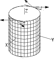

Figure 5.13 Layout of the pre-operational thrusters
Attitude Control in the Operational Phase. Effects perturbing the attitude of the spacecraft include nutation, rotation of the inertial direction of the spin axis, and changes of the spin rate. Nutation (free rotation about an axis different from the symmetry axis, coincident by construction with the axis of maximum inertia) is passively damped by the mechanical coupling of the spacecraft with the PGB.
The tilt of the spin axis is negligible in the time span of the mission, because of the high ratio of spin kinetic energy to magnitude of the perturbing torques. Hence, no control of the spin axis direction is required.
The largest effect producing a change in the spin rate of the spacecraft is due to thermal expansion and contraction of the satellite. The eclipse-sun and sun-eclipse transitions induce thermal expansions and contractions; to conserve angular momentum, the spacecraft inertia changes. Such variations of the satellite spin angular frequency produce a differential angular velocity between the spacecraft and the inner Pico Gravity Box; without any spin control, the relative angular displacement is of the order of 1 rad in one orbital period. The effects due to drag and to solar radiation pressure are negligible with respect to the inertia thermal variation.
The thermal expansion has been modeled assuming that the thermal variation of the inertia is equivalent to the motion of 4 small bodies, symmetrically placed in the equatorial plane of the spacecraft. The distance of the four bodies from the spin axis of the spacecraft is maximum in sunlight phase (maximum expansion of the satellite, maximum inertia) and null in the eclipse phase (maximum contraction of the satellite, minimum inertia). The characteristic time scale of the motion of the four small bodies depends on the thermal time constant of the system, which means on the steady state thermal excursion of the spacecraft and on its thermal penetration depth.
A compensating system of masses, such as that described in Sec. 5.2, can reduce the inertia variation (by expanding/contracting in the opposition with respect to the spacecraft outer shell) to about 10% of the total effect, in the worst case. This residual 10% variation needs an active control. A controller (Proportional-Derivative controller plus low pass filter) capable to compensate the motion of the four bodies was implemented using DCAP; the results show that the spin frequency variations after the control are below the scientific requirements.
Two symmetrically placed pairs of light-emitting diodes can be used to detect the relative phase between Spacecraft and PGB, with a resolution better than 10 m m on a distance of 30 cm, which is 43’’ of degree. The phase coming from the average of the two sensor pairs can be used as input for the spin controller.
Configuration of the Drag Free Control Thruster. The GG drag-free control is treated presented in Chap. 6. Fig. 5.14 shows a possible layout of the FEEP thrusters, providing forces both in the radial and in the longitudinal direction, as well as small torques for residual spin control.
Attitude Sensors Selection. An Earth sensor, able to measure the Earth elevation angle, is preliminarily baselined for GG. For a satellite with momentum bias perpendicular to the orbit plane, there is no indetermination in yaw angle measurement with just an Earth sensor; the satellite orientation is inertially fixed (because of the gyroscopic stiffness) and therefore an error in yaw angle would be detected, after a quarter of orbit, as an error in roll.
An Earth sensor must perform a scanning to detect the Earth limbs and then to derive the attitude angle; the satellite spin can be exploited to perform the required scanning motion (the sensor would be fixed to the satellite with the two optical axes perpendicular to the spin direction). Standard Earth sensors can provide a measurement accuracy compatible with the requirement. For this assessment, we assume the Officine Galileo EES (Earth Elevation Sensor), with the following characteristics:
- mass = 1.4 Kg
- power consumption = 0.7 W
- systematic error = 0.05 °
- random error = 0.01 ° (3s ).
The ESS and a Sun Elevation Sensor can be accommodated in the same housing. The Sun Elevation Sensor is more accurate than the EES (3s random error = 0.01° and systematic error = 0.035° ) and can guarantee partial
attitude determination redundancy in case of EES failure.The characteristics of the GG experiment, requiring highly integrated test mass position control and drag-free control, without any traditional attitude control tasks in the operational phase, naturally lead to a decentralised computer architecture: the payload data processing and control tasks are executed in a dedicated payload computer while the spacecraft data management and pre-operational attitude control are handled by the platform control system.
The spacecraft data management will be based on the Integrated Control System (ICS) architecture adopted in the Prima bus. The ICS includes a Spacecraft Control Unit (SCU) that handles the ground link (telemetry and command) and executes the software performing the platform attitude control, data handling and fault detection and recovery tasks. The SCU software uses a 1553 bus to collect attitude, surveillance and telemetry data and to distribute commands. Attitude sensors and actuators are interfaced through a Remote Unit (RU) that also handles the platform and payload equipment. Data are stored in a modular solid-state Mass Memory Unit. Fig. 5.15 shows the block diagram.
To estimate the telemetry and mass memory storage requirements, two operational modes are introduced:
-Normal scientific mode
-High rate mode (calibration).
In the normal scientific mode, the demodulation of all signals is executed on board at the spin frequency (2 Hz) and only the demodulated signals are transmitted to the ground (hence, at much lower frequency). The exception is the reference spin signal (the same that is used on board for demodulation) that is sampled at 30 Hz frequency and transmitted to Earth for correlation in the data processing. During calibration, and exceptionally to assess the operation of the payload system, the raw data (non demodulated) are collected for up to 10 minutes and later transmitted during the ground contact periods. Table 5.13 shows the housekeeping data rate estimate and Table 5.14 shows the payload data rate estimate.
Housekeeping and auxiliary data rate budgets
Normal Mode
High rate mode
Type
No. records
Record length (bits)
Frequency
(Hz)
Total data rate
(bits/s)
No. x Frequency
Total data rate
(bits/s)
Satellite housekeeping
100
16
1/60
27
27
Payload housekeeping
20
16
1/60
5
5
Thruster commands
8
16
2
256
8x20
2560
Damper commands
3
16
20
960
12x20
3840
Total data rate
1248
6432
Normal Mode
Type
No. records
Record length (bits)
Frequency
(Hz)
Total data rate
(bits/s)
Position of test masses relative to each other [1]
2
16
100/500
6.4
Position of test masses relative to PGB [2]
2x3
16
20/100
19.2
Spin reference signal [3]
3
16
15/0.5
1440
Temperature [1]
1
16
20/500
0.64
Spin axis attitude [1]
2
16
20/500
1.28
Phase difference between PGB and spacecraft [2]
1
16
20/100
3.2
Total data rate
1471
[1] Natural test mass differential oscillation period = 500s
[2] Natural PGB oscillation period = 100s
[3] Spin period = 0.5 s
The total data rate in the normal scientific mode, excluding coding and packet overheads, is 1.25+1.5 kbps, equivalent to about 16 Mbit/orbit, and the normal telemetry rate (before coding and packetising) is 26 kbps, assuming regular 10-minute passes, once per orbit, above the San Marco equatorial station. An on board mass memory sized for 24-hour autonomy would amount to about 240 Mbit. The whole 24-hour memory contents could be downloaded to the ground station in one single pass of 10’ duration at a rate of about half the 1 Mbps maximum rate permitted by the current ESA S-band stations.
In the high-rate mode, the whole scientific data set is stored before demodulation, and the total data rate is close to 100 kbps. However, since 10 minutes of data collection are considered sufficient for payload status assessment, the telemetry rate is on the order of 100 kbps and the mass memory storage capacity required for this mode is 60 Mbit.
5.7 Tracking, Telemetry and Command
The primary functions performed by the Radiofrequency subsystem are:
-Perform phase demodulation on the incoming telecommand signal and provide
the video signal to the on board computer
-Perform phase modulation on the telemetry signals and transmit these signals in S band
through the antennas
-Provide reception and coherent/ non coherent retransmission of ranging signals in order
to perform range and range rate measurements.
The GG radiofrequency subsystem comprises the following units:
-two Antennas
-Radiofrequency Distribution Unit (RFDU), a switch connecting the transponder to the
antennas
-one Transponder, made up of a receiver section and a coherent transmitter section.
The following assumptions have been taken.
-The GG requirements are in agreement with the Radiofrequency and
modulation ESA standard and S+S/X bands coherent transponder specifications.
-The nominal bit rate of the telecommand link shall be 2 kbps, and all the link
performances shall be measured on the basis of this reference figure.
-The telemetry data comprise two major categories: (i) science telemetry, including
scientific data and all the ancillary data necessary for complete and unambiguous
interpretation of the scientific observations; (ii) housekeeping data, for the purpose of:
verification of commanded functions; monitoring of the spacecraft and payload status;
failure detection, diagnosis and recovery actions and for general mission operations and
maintenance functions.
-All the telemetry data are collected and stored by the Mass Memory Unit for
subsequent transmission during periods of visibility with the Ground Station. We assume an
orbit period of 95 minutes and a requirement of 24 hour autonomy without loss of
scientific data.
-The initiation of the telemetry transmission shall be activated only upon reception from
the Ground of a "start telemetry" command.
-The telemetry data shall assure at least a Bit Error Rate (BER) of 10-8 bits.
-The maximum telemetry bit rate is 1 Mbps, including the possible adoption of Reed Solomon
coding to improve the telemetry link margin.
-The protocol telemetry shall be managed by the on board data handling.
-During the pre-operational phase the telemetry data are composed by only housekeeping
data and spacecraft on board time.
-All the performances of the transponder shall be in agreement with the ESA TTC PSS 48
standard. The RF subsystem shall provide an uplink to downlink carrier frequency ratio of
221/240.
-The GG antennas shall provide a continuous omni-directional coverage for any spacecraft
attitude.
Equipment selection
The RF subsystem on board GG is completely standard and any S-band architecture eventually adopted in the PRIMA bus will be applicable. For the purposes of this design exercise, the following assumptions have been made.Antennas: quadrifilar helical antenna (see, e.g., BeppoSAX) with peak gain over 1 dBi and 90° beam width with -3 dBi at the edge. For global coverage, two antennas are used, one located on top of the spacecraft and one on the bottom.
Radio Frequency Distribution Unit (RFDU): the RFDU circuit losses are less than 0.2 dB with a TX signal below 2.5 W. The dimensions are 48× 33× 55 mm and the mass is 200 g. The average electrical consumption is lower than 0.1 W.
Transponder: standard coherent transponder design compatible with the ESA standard. The transmitter is on during the visibility time with the Ground Station. The transponder interface with the decoders which belong inside the OBDH subsystem is via RS422 interface.
Usually all units in the radiofrequency layout are doubled to obtain electrical layout tolerance to any single failure, except the RFDU which is internally redundant, and the reliability of which is very high. For a low cost approach, we assume only one transponder on board the spacecraft, a solution frequently adopted in small spacecraft to save mass and power.
Link Budget
In the evaluation of the link budget we assume that the maximum amount of data (scientific and housekeeping) to be transmitted in a single ground station pass is 240 Mbits. The average visibility time is 600 sec per orbit. Taking into account the synchronisation, the tracking operations and Reed-Solomon coding overhead, different rates of telemetry in the range of: 1.0 - 0.5 Mbps can be selected. In particular, Reed-Solomon coding can be added in real time when the data are transmitted; use of this coding increases the bandwidth by 1.14 times.The GG link budget is evaluated with the ESA database layout and includes a detailed evaluation of the losses on board the spacecraft. The maximum Power Flux Density limits are never exceeded during transmission. A summary of the link budget results is in Table 5.15 below.
Link budget summary
NOM
ADV
FAV
mean- 3sigma
Margin-w.c. RSS
Uplink section Ground Station EIRP dBW 68.76
68.21
68.81
Margin Basic Uplink dB 46.90
40.79
48.29
41.08
42.26
Margin carrier recovery dB 52.43
42.40
55.58
45.09
44.33
Margin telecommand recovery dB 44.57
34.92
47.45
37.31
36.48
Margin transponder ranging-channel dB 38.95
41.85
30.05
Downlink section Spacecraft EIRP dBW -8.75
-12.34
-7.45
Margin over Power Flux Density dB 0.50
-3.24
7.43
Margin carrier recovery dB 19.22
11.02
23.79
12.11
13.89
Margin telemetry recovery with BER= 10-8, TX power =0.3 W, Reed-Solomon coding dB 7.21
1.52
9.50
1.43
2.90
Requirement
0 dB
1 dB
The introduction of Reed Solomon coding allows to increase the link margins without exceeding the allowed Power Flux Density limit, while meeting the required value of BER=10-8. In particular, both the carrier and the telecommand recovery present positive margins greater than the minimum margin required by ESA.
In the downlink budgets the carrier and the telemetry recovery of 1.0 dB for the worst case and the nominal minus RSS case (with these input parameters, 2.90 dB) and 0 dB for the mean value minus three sigma (with these input parameters, 1.43 dB) assure good link margins. The reduction of the internal RF losses on board GGand the adoption of Reed Solomon coding leads to only -5.23 dBW (0.3 W) radiofrequency power.
5.8 Power Supply
The purpose of the Electrical Power Subsystem (EPS) is to generate and to distribute electrical power to all the units on board the spacecraft. Power is generated during the sunlight period (59 minutes), while during the eclipse period (36 minutes) a battery supplies the required energy. From a functional point of view, the EPS is made up of:
Solar Array
Sequential Switching Shunt Regulator (S3R), providing a regulated main bus voltage in output
Battery, to provide electrical energy during ascent phase and the eclipses
Battery Charge Regulator (BCR) and Battery Discharge Regulator (BDR)
Power Protection and Distribution Unit (PPDU), to distribute the electrical power to all the subsystems in the spacecraft. Each outlet is protected against short circuit and overcurrent by electronic fuses.
A possible implementation of the EPS for GG is described below (see the block diagram of Fig. 5.16). The final subsystem architecture will be based on that provided by the PRIMA bus.
Figure 5.16 Power subsystem block diagram
Gallium Arsenide (GaAs) cells are provided as part of the Prima bus complement, with photovoltaic conversion efficiency of 19%. Hence, after accounting for radiation, pointing and packing factor losses, as well as for a small positive power contribution from the Earth reflected sunlight, the specific power is on the order of 190 W/m2. The body mounted solar array consists of two cylindrical sections with a total efficient area of 0.97 m2; hence the power delivered by the array is 185 W.
A preliminary assessment of the power demand of the spacecraft gives about 110 W (see Table 5.20). The mission consists of one running experiment, therefore there is no significant difference between the power demand in sunlight and in eclipse. 72 W are needed to recharge the battery during the sunlight period, compatible with the array power but without any system margin. If Pegasus remains the reference launch vehicle, the power demand must be kept under strict control in the detailed design phase of the project, since the XL fairing diameter and height do not allow any significant increase of solar array size; on the other hand, ample margins for increasing the solar array area exist in the option of the Vega (or any other) launcher.
A suitable battery comprises 32 cells with a 3.5 Ah capacity. Such cells, already space qualified, are produced by SAFT (VR 3.5 DE). The overall weight, including 13% contingency margin in the structure, is 5 kg and the volume is 2.5 liters (260× 150× 80 mm as preliminary assumption). This battery presents an equivalent magnetic moment of Mm= 0.049 Am². This battery is sufficient for up to 1 hour ascent plus 1 orbit for activation of all on board subsystems, under the assumption of a pre-operational power demand as in Table 5.9-3.
For the Battery Discharge Regulator a simple diode (internally redundant) could be sufficient. The diode is active when the voltage on the main bus is under the battery voltage. This solution is lighter and cheaper with respect to the common approach in which a dedicated electronic circuit maintains constant the main bus voltage during the discharge of the battery.
For the battery charge regulation, a hybrid bus using two separate S3R's: one for the main bus and one for the battery charging, could be adopted, with advantages in terms of mass (no BCR modules) and power consumption. The S3R is a switching system with one dump always switching on/off and the other dumps either on or off depending on the solar array power available and the satellite load requirements. The use of hexfets, or similar technology, simplifies the drive to the switching devices and further reduces the power dissipation. Hence it is possible to include in a single box S3R, BDR and the PPDU. The bus voltage is 28 V ± some percent during the sunlit phase, while in eclipse it decreases from 28 V to 24 V.
A cost saving implementation of the Power Protection and Distribution Unit would be based on the following rules: (i) a single, non redundant, outlet for each subsystem; (ii) the central computer is in charge of telemetry acquisition from each outlet, via dedicated lines. Each outlet can be switched on/off via telecommand except the receiver, the OBDH and the AOCS sensors. Further each outlet has the capability to withstand a short circuit and hence to reduce the output current with fold back protection.
On the basis of the previous description, a single box would be sufficient, including all the functions in the EPS, except the battery. The preliminary dimensions of this unit are 225× 175× 160 mm and the weight is close to 7 Kg. The few telemetry and telecommand lines are activated directly by the OBDH.
Table 5.16 Satellite Mass Budget
Centre of Mass and Moment of Inertia Budget
Spacecraft only 1
Total satellite
Centre of mass (mm) 2 Z 424.
424.
X, Y < 0.2
< 0.12
Moments of Inertia (kg m²) 3 IZZ 27.46
32.25
IXX 21.09
25.18
IYY 21.77
25.86
1
Excluding PGB and test masses
2 Reference frame with origin at the intersection of the separation plane with the symmetry axis (Z)
3 Ijj = moments of inertia about the principal axesTable 5.17
|
|
Pre-operational (W) |
Operational (W) |
| Payload | ||
| PGB electronics | 0 |
6 |
| FEEP electronics | 0 |
60 |
| Subtotal Payload | 0 |
66 |
| Service Module | ||
| RF | 8 |
8 |
| Integrated Control System | 12 |
12 |
| Heaters | 10 |
10 |
| AOCS sensors | 1 |
1 |
| Harness | 4 |
4 |
| EPS | 11 |
11 |
| Subtotal Service Equipment | 46 |
46 |
| Total Satellite | 46 |
112 |