Open
discussion on International
Workshop Theses What's going on....
|
As technical staff of ESA at ESTEC, Y. Jafry and M. Weinberger have studied the GG experiment. They eventually published their technical report on Class. Quantum Grav. (1998, 15, 481-500) under the title: Their conclusion, that GG is limited to a sensitivity in testing the equivalenc principle no better than 1 part in 1015 (2 orders of magnitude less sensitive than expected by the proposers) was disproved in a following paper by the GG team papers published on the same Journal under the title: "Evaluation of a Proposed Test of the Weak Equivalence Principle Using Earth-Orbiting Bodies in High-Speed Co-Rotation: Re-establishing the Physical Bases" (Class. Quantum Grav, 16, 1463-1470, 1999) (see also below paper to navigate). The Journal refused to publish the counter response by Jafry& Weinberger to this paper, and they never wrote anything on this issue ever since. Ready to print (212 KB): Classical and Quantum Gravity, vol 16 pp 1463-1470, 1999 EVALUATION of a PROPOSED TEST of the WEAK EQUIVALENCE PRINCIPLE USING EARTH-ORBITING BODIES in HIGH-SPEED Co-ROTATION: Re-ESTABLISHING the PHYSICAL BASES A M Nobili1, D Bramanti1, E Polacco1, G Catastini2, A Anselmi2, S Portigliotti2, A Lenti3, P di Giamberardino4, S Monaco4, R Ronchini4 1Universitŕ di Pisa, 2Alenia Spazio Torino, 3Laben Milano, 4Universitŕ di Roma "La Sapienza" Italia ABSTRACT Test masses coupled by weak mechanical suspensions are sensitive to differential forces such as the force due to a possible violation of the Equivalence Principle (EP). If in addition they are put in rapid rotation, the differential signal is modulated at high frequency, which is beneficial for noise reduction. GALILEO GALILEI (GG) is a proposed space experiment for testing the Equivalence Principle to 1 part in 1017 based on these concepts. Paper [1] claims that GG can only reach 10-14. We show that the analysis of [1] is flawed (by several orders of magnitude) because of two misconceptions: one on the physical nature of mechanical damping and the other on active control methods for the stabilization of spinning bodies. 1. INTRODUCTION Paper [1] has been devoted to the GG space experiment [2-4] addressing the issue of the stabilization of whirl motions that weakly coupled rotors are known to develop because of non zero dissipation between rotating parts of the system. The conclusion of [1] is that the required stabilizing forces overcome by far the weak passive forces of the mechanical suspensions (springs) on which the GG experiment relies, thus making it inadequate for a very high accuracy EP test. We show that [1] is affected by two serious misconceptions which invalidate in full its conclusions: a misconception on the physical nature of mechanical damping (Sec. 2) and a misconception on the active control of spinning bodies (Sec. 3). GG is a small satellite project aiming at testing the Equivalence Principle to 10-17 with concentric hollow test cylinders in rapid rotation around their symmetry axes. The test bodies are suspended and coupled by very weak mechanical suspensions; the corresponding frequencies of natural oscillations are much smaller than the spin frequency. The experiment is run at room temperature; the spacecraft is spin-axis stabilized and no active attitude control is needed. In the current version, non gravitational forces acting on the spacecraft surface are largely compensated by FEEP ion thrusters needing only a few grams of propellant for the entire mission duration. If the test bodies fall differently in the field of the Earth because of an EP violation their centres of mass will show a relative displacement, pointing to the centre of the Earth, whose amplitude depends on the stiffness of the differential mechanical coupling. Such mechanical displacement is transformed into an electric potential signal via a capacitance read-out system whose plates are located halfway in the gap between the coaxial test cylinders. Since the plates spin with the system (at @ 5Hz), the signal is modulated at this frequency. In the original torsion balance experiments by Eötvös the signal was DC. Subsequent experiments with better results (finding no violation to level of @ 10-12) were based on modulation frequencies at least 5 to 4 orders of magnitude smaller than that proposed in GG: 24 h in [5,6] and 2 h in [7]. As of this writing, GG is 1 of 6 projects selected and funded for Phase A Study by the Italian Space Agency (ASI) [8]. Information on GG is available on the Web [9]. 2. MISCONCEPTION ON THE PHYSICAL NATURE OF MECHANICAL DAMPING GG is constructed of rigid bodies coupled by weak suspensions of high mechanical quality (particularly those of the test bodies) which moreover undergo only minute deformations (a few mm at most). The suspensions are carefully clamped so as to avoid parts sliding one against the other, which is the main cause of mechanical losses in the clamps and in the whole system. There are no bearings, since, after spin up is completed, there is no need of a motor. There are no viscous materials: no fluids, no oils, no greases. Therefore the main loss factors (inverse of quality factor Q) are those due to the very small internal dissipation of the mechanical suspensions as they undergo minute deformations at the spin frequency. The only other cause of dissipation are the electrostatic sensors/actuators used to damp the whirl motions, since all other parts are rigid and have no losses. Calculation of thermal noise in the active dampers shows that the corresponding losses are by far negligible compared to those achievable with mechanical suspensions [4,10] (assuming all parameters as for the GG experiment and a very conservative value of 10 for the electric quality factor). Crandall [11] has calculated (using [12]) the back-reaction force on the plates of the capacitors from the high-frequency measurement voltage, finding that the electrical contributions to the mechanical stiffness and damping are negligible. Losses in the dampers will be measured with the GG prototype on the ground after active rotating control, similar to the GG active control, has been implemented [13, Chap. 3]. A firm estimate of the losses in the GG mechanical suspensions requires them to be measured experimentally, by setting the springs in oscillation under realistic operating conditions (oscillation frequency, vacuum, temperature, clamping); note that there is no need to perform this measurement with the system rotating [14] In order to measure, for a given mechanical system, the quality factor Q (defined as the ratio of the total energy stored in the system to the amount of energy dissipated in one cycle) the system is made to oscillate and then the oscillation amplitude A(t) is recorded as it decays with time. Q can also be defined as follows:
 (4)
where m is the reduced
mass of the system. Because of the misconception on the nature of damping, [1]
erroneously gets the time-scales of whirl
motion to be a factor ws/wn shorter (5.6 s for the PGB and 0.7 h for the test masses) and the forces (4) a
factor ws/wn larger; hence, also the effects of imperfections and errors in these forces are
amplified by the same factor.
 3. MISCONCEPTION ON ACTIVE CONTROL METHODS FOR THE STABILIZATION OF SPINNING BODIES The GG bodies are stabilized actively, by means of small capacitance sensors/actuators rotating with the system at a velocity @ 103 times higher than the velocity of whirl they are required to damp. In order to recover and damp this slow (and slowly growing) velocity with much more rapidly rotating sensors/actuators we have developed a control strategy [15, 17,13] in which: the relative velocity of the bodies is computed from differences of measurements taken by the rotating displacement sensors 1 spin period apart 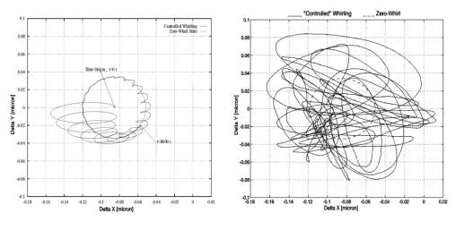 Figure 1. Trajectory of the relative motion of the centers of mass of the GG
outer spacecraft and the PGB in the plane perpendicular to the spin axis in a 2-body model
(coupling constant 0.02 N/m, Q=90). The Y axis is pointed to the center of the Earth,
hence the largest effect of the residual atmospheric drag, assumed of 5× 10⁻⁹
N, is a constant displacement along the X axis (of @ 0,08 mm); its second harmonic (assumed 40% of it) appears in
this system as a variation at the orbital period (5,700 s). This is the dashed circle,
showing -in both plots- the stationary state that the system would reach if the whirl
motion were perfectly damped. The plot on the left is obtained with the control laws of
the GG Team assuming the following errors:
initial bias of 10 mm linear and 1° angular; fractional error in spin rate measurements Dws/ws=10-4; offset (by construction and mounting) of
10 mm; errors in the
capacitors of 0.1 mm RMS. Whirl oscillations with the natural period of 314 s
(around the points of the dashed circle) and of decreasing amplitude are apparent as the
system is brought to its stationary state in 8,000 s only. Note that at this point the
relative distance of the two centers of mass is below 5 Ĺ . These results have been
obtained independently using DCAP software package (of Alenia Spazio) and Matlab. The plot
on the right shows, for the same system, but under much more ideal assumptions (perfect
knowledge of spin rate; perfect centering of the rotor; an initial linear bias of 1m m and
no angular bias; an error in the sensors/actuators 10 times smaller, i.e. of 10-2
mm) the results obtained by applying the control laws proposed in paper
[1]. It is apparent that even in a much more favorable situation the same
system has been unwittingly transformed into one dominated by very large active forces for
which there is in fact no need, as the plot on the left demonstrates. Note that the
dissipation has been assumed to be the same in both cases (Q=90), hence failure to
stabilize the whirl motion (right hand plot) has to be ascribed only to the control laws
implemented in that case. Regarding the plot on the left note that the assumptions for the
various error sources are conservative. For instance, small capacitors like those designed for GG can be shown in the laboratory to be sensitive to relative
displacements of 10-2 mm.
Since the control laws used in [1] fail so heavily already in the simpler 2-body model, they are certainly
useless for the scope claimed in the paper, that is to evaluate the sensitivity achievable
in EP testing by the full 6-body GG system.
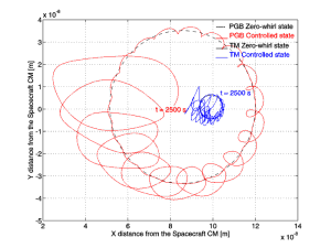
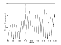
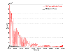
How the full GG system ( 4 bodies plus 2 small coupling arms) is stabilized by controlling all whirl motions at the same time is shown in Figure 2. The resulting relative distance between the test bodies is shown in Figure 3, while Figure 4 gives the intensity of both the passive elastic force and the control force.Figure 2. Evolution of the full 6-body GG system: outer spacecraft, PGB, two test masses with two gimballed coupling arms. These arms are pencil-like in shape and have no rings. As individual bodies they would be unstable; in GG they couple two much more massive test bodies which are individually stabilized by whirl control, hence, also the arms are found to be automatically stabilized with no need of adding rings around their midpoints. Only the trajectories of the PGB and of one test mass are plotted (for 9,500 s after the first 2.500 s) showing their distance from the center of mass of the spacecraft (0,0). The plane of the Figure is perpendicular to the spin axis and the Y axis is pointed to the center of the Earth. The residual drag acting on the spacecraft has a DC component equal to 5 × 10⁻⁹ N (giving rise to a constant X displacement in this plot) plus an orbital frequency term which is 40% of the DC component (giving rise to the dashed circles) and a 10% noise on both components. Whirl motions appear as oscillations at the natural periods around the points of the corresponding dashed circles: if active control is effective their amplitude must decrease. This is indeed what happens. Here we have assumed Q values of 90 for the PGB and 500 for the test masses (a very conservative assumption for the test masses, since the measured Q for their suspensions is of 16,000¸19,000). The errors included were: 10-2 mm RMS (tested in the laboratory for capacitance plates of @ 2 cm2 as in the GG active dampers), 10 mm linear bias, 1° angular bias for the capacitance sensors; Dws/ws = 10-4 RMS for the Earth Elevation Sensors (doable with EES by "Officine Galileo", Firenze); 1 mm initial offset of the suspension springs. Figure 3. Numerical simulation of the same 6-body GG system as in Figure 2, with the same residual drag and the same error sources. Here we plot the relative displacement between the inner and the outer test mass (differential displacement) as obtained after applying active control of their whirl motions. Note that in this simulation whirl control is always on, i.e. this is a worst case simulation because whirl control can in fact be switched off during scientific data acquisition. This result is impressive in that it shows how active control by means of electrostatic sensors/actuators can be so accurate as to make the GG macroscopic test bodies self-center on one another as expected in supercritical rotation in absence of dissipation (infinite mechanical quality factor, zero-whirl). Figure 4. Numerical simulation of the 6-body GG system with the same error sources as in Figures 2 and 3. Here we plot the passive elastic force of the suspension springs (in red) for comparison with the control force acting on the outer test mass (in black). The control force is clearly much smaller than the elastic force. We recall that, in order to speed up the simulation, the quality factor of the test bodies suspension springs was taken to be 500 (4 times worse than measured); in addition, the system was controlled with a force 11 times larger than the minimum required theoretically by (4). In point of fact, we have also run experiments in which a control force only 2.5 times larger than the minimum could stabilize the system. Figures 2¸ 4 refer to planar simulations; simulations in 3-D have been carried out [13, Chap. 6] showing that the dynamical behavior is not affected by the increased number of degrees of freedom; however, the required computing time increases significantly. As for the effect of drag (and of solar radiation pressure), it is huge compared to the expected signal; however, it is transferred to the test masses as an inertial acceleration in common mode by its nature, while an EP violation signal would be differential. This is why the GG test cylinders are arranged in a coupled suspension similarly to an ordinary beam balance (except for the fact that the beam is vertical rather than horizontal): by adjusting the length of the arms with piezoelectric actuators common mode forces can be rejected leaving only a much smaller differential effect to compete with the signal. In physics experiments this is known as Common Mode Rejection; the attainable level of rejection depends on the specific system and mechanism for rejection. With the prototype of GG in the laboratory we have achieved a rejection level of 1 part in 200,000, which is better than the current requirement for the GG experiment in space [13] where we assume that drag is partially compensated (by drag-free control with FEEP mini-thrusters), and partially rejected. Drag could also be totally rejected (no compensation) [4] provided the rejection level is improved accordingly. The drag-free control of GG is based on a notch filter at the orbital frequency [13, Chap. 6]; it has been tested in combination with whirl control for the full 6-body GG system also in 3-D. No additional difficulties are encountered in the 6-body case as compared to the 2-body model, but the computing time required by the simulations is much bigger. 4. CONCLUSIONSWe have shown that paper [1] overestimates the required stabilizing forces of the GG system by a factor w s/w n @103 because of a misconception on the physical nature of mechanical damping. In addition, it overestimates the active control forces to be applied by rotating sensors/actuators by another factor ws/wn because of a misconception on the control laws of spinning bodies. Overall this amounts to an error by a factor @106. This invalidates in full the evaluation of GG as carried out in [1], according to which GG could only reach a sensitivity in EP testing of 1 part in 1014. Paper [1] is the final version of a precursor technical report [18] prepared by the same authors in support of the Fundamental Physics Advisory Group (FPAG) of ESA for its evaluation of GG [19]. Therefore, we can also answer a few questions raised in [19]. In particular: (i) [19] states that "The high spin rate is not an advantage for the experiment. The advantages conveyed by spin (suppressing the effects of low-frequency noise) are outweighed by the disadvantages of having unstable modes around the signal frequency." Instead, unstable modes can be stabilized and they are so slow that scientific data acquisition can take place while whirl control is off, hence the advantages of high spin rate can be fully exploited; (ii) [19] states that "The servo forces will dominate the passive spring forces." Instead, we have implemented control forces which are by far smaller than the elastic forces and yet can stabilize the whirl motions (Figures 4,2,3); (iii) [19] states that the gimballed rods (the coupling arms) "..appear to be highly unstable in high-speed rotation and are a source of significant perturbations." Instead, numerical simulations of the full GG system show that this is not the case (further details in [13, Chap. 6]), confirming the physical guess made by the GG Team before a full simulation could be carried out; (iv) [19] states that "The control forces have to mimic damping forces in the non-rotating frame but must be synthesized from measurement in the rotating frame. Imperfections in the sensors and actuators will cause significant disturbances in the differential mode." The first statement is true, but the second one has been found to be wrong if control forces are properly computed and applied; which is not the case in [18, 1]. Another issue raised in [19], that of the usefulness of the PGB laboratory has not been touched here; it has been answered in [15;13, Fig. 2.6].REFERENCES [1] Jafry Y and Weinberger M 1998 Class. Quantum Grav. 15 481-500 [2] Nobili A M et al 1995 J. Astronaut. Sci. 43 219-42 [3] GG Pre-Phase A Report, ASI (1996) [4] Nobili A M et al 1998 New Astronomy, 3 175-218 [5] Roll P G, Krotkov R and Dicke R H 1964 Ann. Phys. 26 442-517 [6] Braginsky V B and Panov V I 1972 Sov. Phys. JEPT 34 463-466 [7] Su Y et al 1994 Phys. Rev. D 50 3614-3636 [8] "Italy selects finalists for satellite mission" 1997 Nature 390 546 [9] GG Project Web Page http://tycho.dm.unipi.it/nobili/ggproject.html [10] Nobili A M, Catastini G and Bramanti D 1997 "GG: Dissipation by the Electrostatic Dampers" http://tycho.dm.unipi.it/nobili/ggweb/qdampers/qdampers.html [11] Crandall S H, 1997 private communication [12] Braguinski V et Manoukine A. 1976 "Mesure de petites forces dans les expériences physiques" Editions Mir, Moscou [13]GG Phase A Report, ASI (1998) http://tycho.dm.unipi.it/nobili/ggweb/phaseA/index.html [14] Crandall S H and Nobili A M 1997 "On the Stabilization of the GG System" http://tycho.dm.unipi.it/nobili/ggweb/crandall/crandall.html [15] Nobili A M et al 1996 in "Scientific Satellites Achievements and Prospects in Europe" Proceedings AAAF-ESA 74-89 [16] Crandall S H 1970 J. Sound Vib. 11 3-18 [17] Addendum No. 1 to GG Pre-Phase A Report, ASI 1997 http://tycho.dm.unipi.it/nobili/ggweb/addendum/addendum.html [18] Cornelisse, J. W., Y. Jafry and M. Weinberger "Technical Assessment of the GALILEO GALILEI (GG) Experiment, ESTEC (here reference is only to the part on dissipation and active control due to Jafry and Weinberger), 1996 [19] ESA, Fundamental Physics Advisory Group, FPAG(96)4, 1996 http://tycho.dm.unipi.it/nobili/ggweb/referee/fpag.html anna nobili |
|---|
 (2)
(2) (3)
(3)