A schematic view of the apparatus is given in
Fig. 2, where a section through the spin/symmetry axis of the accelerometer is shown (enclosed by the vacuum chamber). (The color version of Fig. 2 is available in the article published on the World Wide Web.) Fig. 3 shows a picture of the accelerometer mounted inside the chamber. In Fig. 2 the chamber and the frame (not rotating) on which the whole rotor is mounted are drawn in gray. The test cylinders are drawn in green (the inner one) and blue (the outer one). On the top of the frame (at its center) is a shaft turning inside ball bearings (sketched as "x" in the section of Fig. 2) to which rotation is transmitted from the motor by means of O-rings on pulleys. This shaft holds the suspension tube, which therefore rotates with the shaft. Inside the suspension tube is the coupling arm (also a tube) suspended at its midpoint from the suspension tube by means of a laminar suspension (drawn in red; see picture in Fig. 4). The two test cylinders are suspended from the two ends of the coupling arm (the outer one from the top, the inner one from the bottom) by two more laminar suspensions (all three suspensions are manufactured to be equal; they are all drawn in red in Fig. 2). Being metallic, they also ensure passive electrostatic discharging of the test masses. Fig. 3 shows three light vertical bars and a horizontal ring used to connect the outer test cylinder to its suspension at the top of the coupling arm. The suspensions have the property of being soft in both the X and Y directions in the plane perpendicular to the symmetry/vertical axis, while at the same time being strong enough in the vertical direction in order to withstand local gravity. In this way the test cylinders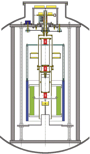
Fig. 2. Section through the spin axis of the differential accelerometer inside the vacuum chamber (drawing to scale; inner diameter of vacuum chamber 1 m; see text for a description of its parts).
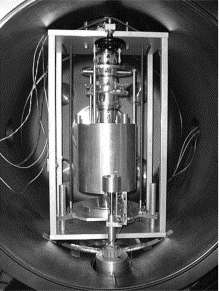
Fig. 3. The rotating differential accelerometer mounted inside the vacuum chamber (in the basement of the LABEN laboratories in Florence).
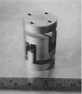
Fig. 4. One of the three laminar suspensions used in the accelerometer (sketched in red in Fig. 2). They are carved out of a solid bar of CuBe by electroerosion in 3D and properly treated for high mechanical quality.
The read-out consists of two pairs of capacitance plates located halfway in between the test cylinders and connected to the suspension tube by means of an insulating frame (see picture in Fig. 5 and section in Fig. 2, in which they appear as vertical lines in between the test cylinders). They maintain the cylindrical symmetry of the system, forming two capacitance bridges in the X and Y directions of the plane perpendicular to the symmetry axis (the plane of sensitivity of the instrument). The two annular dishes (in yellow) mounted around the upper half of the suspension tube contain the two capacitance bridge circuits, their preamplifiers, the signal demodulators, the A/D (analog-to-digital) converters and the driver of the optical emitter, which is located at the very top of the rotating shaft (in order to transmit the demodulated signal from the rotor to the non-rotating frame and then outside of the vacuum chamber). In the upper part of the shaft, above the ball bearings, are the rotating contacts for power transmission to the electronics of the rotor and a dish with a circuit for stabilizing this power. To this dish is also attached an optical device which provides a reference signal for the phase of the rotor. The passive damper is shown under the lowest laminar suspension, and is not rotating (see Section 4).
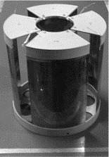
Fig. 5. The four capacitance plates (with their insulating frames) forming the two capacitance bridges of the read-out. They are mounted halfway in between the concentric test cylinders to read their relative displacements (see section in Fig. 2).
A differential force acting between the test cylinders in any direction in the
horizontal plane of the laboratory will incline the balance beam![]() pivoted at its midpoint
pivoted at its midpoint![]() with respect to
the vertical, thus giving rise to a relative displacement of the centers of mass of the
cylinders in the direction of the force. The resulting mechanical displacement will
unbalance the capacitance bridges, thus allowing it to be transformed into an electric
voltage signal. If the whole system (test cylinders plus read-out) rotates around the
vertical shaft, the signal is modulated at the rotation frequency, just as in the GG space
experiment (Fig. 1). In case of an EP violation in the field
of the Earth, two test cylinders of different composition should show (after
transformation to the non-rotating reference frame) a constant, relative displacement in
the North-South direction of the horizontal plane. Instead, checking for violation in the
field of the Sun requires to detect a (smaller) relative displacement vector in the same
plane following the Sun in its daily motion with respect to the Earth fixed laboratory
where the test bodies are located.
with respect to
the vertical, thus giving rise to a relative displacement of the centers of mass of the
cylinders in the direction of the force. The resulting mechanical displacement will
unbalance the capacitance bridges, thus allowing it to be transformed into an electric
voltage signal. If the whole system (test cylinders plus read-out) rotates around the
vertical shaft, the signal is modulated at the rotation frequency, just as in the GG space
experiment (Fig. 1). In case of an EP violation in the field
of the Earth, two test cylinders of different composition should show (after
transformation to the non-rotating reference frame) a constant, relative displacement in
the North-South direction of the horizontal plane. Instead, checking for violation in the
field of the Sun requires to detect a (smaller) relative displacement vector in the same
plane following the Sun in its daily motion with respect to the Earth fixed laboratory
where the test bodies are located.
The instrument is therefore a rotating differential accelerometer sensitive in the horizontal plane. Its differential character comes from two features. The first is that the test cylinders are mechanically coupled so as to be sensitive to differential accelerations acting between them because of the geometry of their mounting. The second is that the read-out too is differential: were all plates mounted exactly halfway in between the test cylinders (same clear gap on either side), it would be totally insensitive to common mode forces (i.e., to forces causing a displacement of both test cylinders together with respect to the capacitance plates). For a non-zero off-centering of the plates between the cylinders, the read-out is anyway less sensitive to common mode displacements than it is to differential ones, by a factor which is the ratio of the off-centering to the average gap: the better the plates are centered, the less sensitive is the read-out to common mode forces, the more suitable it is for EP testing. The sensitivity of the test cylinders to differential accelerations depends on the softness of the laminar suspensions and the balance of arms and masses in their coupled mounting. Soft suspensions and good balancing are needed, providing long natural periods of differential oscillations of the test cylinders with respect to one another. The longer the natural periods of differential oscillations, the larger the mechanical displacements of the test cylinders in response to differential accelerations, the stronger the output voltage signal. Soft suspensions and good balancing are also needed in order to reduce the residual differential fraction of forces which are common mode by their nature but do in fact produce also a differential effect on the test cylinders due to the inevitable imperfections in their mounting and balancing. Ideally, a common mode force should be perfectly rejected by the system, leaving no differential residual. By comparison, the test cylinders of the ÁSCOPE accelerometer (also based on capacitance sensing) are controlled with respect to the same silica frame but are not coupled, neither by the suspensions (each cylinder has its own electrostatic suspension) nor by the read-out (the differential data of interest are obtained as the difference of the individual readings of the capacitance sensors of each test cylinder (MICROSCOPE Website: http://www.cnes.fr/activites/programmes/microsatellite/1sommaire_microsatellite.htm and http://www.onera.fr/dmph-en/accelerometre; Touboul et al., 2001, Fig. 1).
Ordinary beam balances are known to be ideal instruments for extremely effective common
mode rejection (rejection factors of 10![]() 8
8![]() 10
10![]() 9 can be reached at 1-g). Also in the
accelerometer designed for space (see Fig. 6 and its caption;
the color version of Fig. 6 is available in the article
published on the World Wide Web) the test cylinders are coupled like in a beam balance
9 can be reached at 1-g). Also in the
accelerometer designed for space (see Fig. 6 and its caption;
the color version of Fig. 6 is available in the article
published on the World Wide Web) the test cylinders are coupled like in a beam balance![]() with the plane of
sensitivity perpendicular to the beam as in Fig. 2
with the plane of
sensitivity perpendicular to the beam as in Fig. 2![]() and have a
differential capacitance read-out. The geometry of the space accelerometer is perfectly
symmetric, which is possible in the absence of weight because the direction of the beam is
not the direction of a force many orders of magnitude larger than any force acting in the
sensitivity plane perpendicular to it, as it is the case with the vertical balance of Fig. 2 because of the local acceleration of gravity. In this
case the advantage of the coupling of the test cylinders is retained in spite of a lack of
symmetry in their suspension arms: the center of mass of the inner cylinder is very close
to its suspension point, while the center of mass of the outer one is much farther from
its own (see Fig. 2). This asymmetry is a consequence of the
special character of the vertical direction when operating at 1-g and it is an inevitable
change from the perfect symmetry of the space design.
and have a
differential capacitance read-out. The geometry of the space accelerometer is perfectly
symmetric, which is possible in the absence of weight because the direction of the beam is
not the direction of a force many orders of magnitude larger than any force acting in the
sensitivity plane perpendicular to it, as it is the case with the vertical balance of Fig. 2 because of the local acceleration of gravity. In this
case the advantage of the coupling of the test cylinders is retained in spite of a lack of
symmetry in their suspension arms: the center of mass of the inner cylinder is very close
to its suspension point, while the center of mass of the outer one is much farther from
its own (see Fig. 2). This asymmetry is a consequence of the
special character of the vertical direction when operating at 1-g and it is an inevitable
change from the perfect symmetry of the space design.
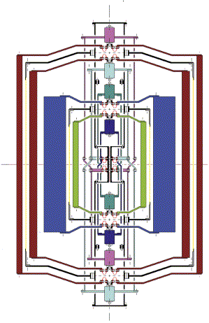
Fig. 6. Section through the spin axis of the differential accelerometers of the proposed GG mission for testing the equivalence principle in low Earth orbit. There are four test cylinders (10 kg each), one inside the other, all centered at the same point (nominally, the center of mass of the spacecraft) forming two differential accelerometers: the inner one for EP testing (cylinders of different composition; shown in green and blue respectively) and the outer one for zero check (cylinders made of the same material; both shown in brown). In each accelerometer the two test cylinders are coupled to form a beam balance by being suspended at their top and bottom from the two ends of a coupling arm made of two concentric tubes (each tube suspends one test cylinder at each end, which makes it asymmetric top/down; however, the two of them together form a symmetric coupling). All four tubes (two for each coupling arm) are suspended at their midpoints from the same suspension shaft (the longest vertical tube in figure). In all cases the suspensions are
-shape (or
-shape) thin strips (shown in red), to be carved out of a solid piece of CuBe. At each connection there are three of them, at 120░ from one another (the planar section in figure shows two for explanatory purposes only). There are capacitance plates (connected to the suspension shaft) for the read-out of differential displacements in between each pair of test cylinders (shown as yellow lines in section).The eight small cylinders drawn along the symmetry axis are inchworms for the fine adjustment of the lengths of the coupling arms in order to center each test mass on the center of mass of the spacecraft. The whole system is symmetric around the spin axis as well as top/down. The two accelerometers are both centered at the center of mass of the spacecraft in order to reduce common mode tidal effects and improve the reliability of the zero check.
It is desirable that the spin rate be high, so as to get a correspondingly high frequency modulation of the signal and consequent reduction of 1/f mechanical and electronic noise. It is also desirable for the mechanical coupling between the test cylinders to be weak (long natural differential period Tdiff), for them to be sensitive to differential forces like the one which would result from an EP violation, because the relative displacement due to a differential force increases as Tdiff2). This means that typically the system spins at a frequency higher than the natural frequency for differential oscillations of the test cylinders, in which case it is known that the spinning bodies do reduce any original offset vector between their centers of mass (fixed in the rotating system) inevitably due to imperfections in construction and mounting (see e.g. Den Hartog, 1985; Crandall, 1995; Genta, 1993). In simple terms, a weakly coupled and fast spinning rotor is an approximation to an ideal unconstrained rotor whose center of mass would have zero offset from the rotation axis.
The natural period Tdiff for differential oscillations of the test cylinders, one with respect to the other, in the vertical beam balance arrangement of Fig. 2 (in the presence of both local gravity and mechanical coupling) can be written as:
(1)
with m the mass of the test cylinder, g the local acceleration of
gravity, 2l the length of the coupling arm (with a difference ![]() l>0 between its lower and upper half
respectively) and K the coupling constant (note that, for lateral flexures, K
is lower than the elastic constant of the laminar suspensions shown in Fig. 4 and Fig. 2 by a factor given
by the ratio, squared, of the length of the laminar suspension itself to the length l
of the arm
l>0 between its lower and upper half
respectively) and K the coupling constant (note that, for lateral flexures, K
is lower than the elastic constant of the laminar suspensions shown in Fig. 4 and Fig. 2 by a factor given
by the ratio, squared, of the length of the laminar suspension itself to the length l
of the arm![]() "lever
effect"). In Eq. (1) the ratio
"lever
effect"). In Eq. (1) the ratio ![]() l/l accounts for both the balance
of arms and masses (
l/l accounts for both the balance
of arms and masses (![]() m/m)
attached to the beam. The validity of Eq. (1) is confirmed by
numerical simulations and measurements, and shows well the relevance of gravity. If
m/m)
attached to the beam. The validity of Eq. (1) is confirmed by
numerical simulations and measurements, and shows well the relevance of gravity. If ![]() l>0, gravity acts as a positive spring,
thus increasing the stiffness of the coupling, i.e. reducing the length of Tdiff. Instead, if
l>0, gravity acts as a positive spring,
thus increasing the stiffness of the coupling, i.e. reducing the length of Tdiff. Instead, if ![]() l<0, gravity acts as a negative spring
and the ratio
l<0, gravity acts as a negative spring
and the ratio ![]() l/l (indeed,
l/l (indeed, ![]() l/l and/or
l/l and/or ![]() m/m) can be adjusted so as to
reduce the denominator of Eq. (1) whereby increasing the value
of Tdiff. We have
verified this, obtaining differential periods of up to about 90 s, although so far the
accelerometer has been operated with differential periods around 10 s.
m/m) can be adjusted so as to
reduce the denominator of Eq. (1) whereby increasing the value
of Tdiff. We have
verified this, obtaining differential periods of up to about 90 s, although so far the
accelerometer has been operated with differential periods around 10 s.
Natural differential oscillations in the X and Y directions as detected
by the capacitance read-out are shown in Fig. 7 (zero spin
rate, differential periods of 11 s). When the rotor spins at 3 Hz the differential
displacements between the test cylinders measured by the (rotating) capacitance bridges
show the same natural periods, in addition to the expected rotation frequency (see Fig. 8). At zero spin the decreasing amplitude of oscillations
allows the quality factor Q of the system to be measured, yielding an average value
of 510. The dominant losses are due to the laminar suspensions of the rotor as deformed at
the low natural differential frequencies, and for large oscillation amplitudes (up to 1
mm). Q measurements for the laminar suspensions alone![]() before assembling of the accelerometer
before assembling of the accelerometer![]() when set in
horizontal oscillations at higher frequency (5 Hz) and similar oscillation amplitudes,
have been performed (in vacuum), yielding Q values of 2000 ("GALILEO
GALILEI" (GG), Phase A Report, 1998, Section 3.4; Nobili et al.,
2000). Better (higher) Q values are expected at higher frequencies and for
smaller oscillation amplitudes. However, once rotating, the suspensions are deformed at
the frequency of spin and losses occur at this frequency, which is higher than the
differential frequency, and should therefore result in higher Q's (see Section 5).
when set in
horizontal oscillations at higher frequency (5 Hz) and similar oscillation amplitudes,
have been performed (in vacuum), yielding Q values of 2000 ("GALILEO
GALILEI" (GG), Phase A Report, 1998, Section 3.4; Nobili et al.,
2000). Better (higher) Q values are expected at higher frequencies and for
smaller oscillation amplitudes. However, once rotating, the suspensions are deformed at
the frequency of spin and losses occur at this frequency, which is higher than the
differential frequency, and should therefore result in higher Q's (see Section 5).
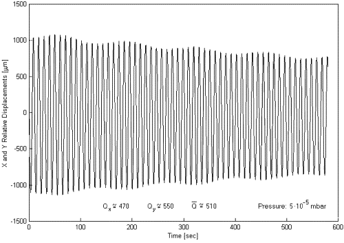
Fig. 7. Relative displacements, in the X and Y directions of the sensitivity plane, between the centers of mass of the test cylinders at zero spin rate. The natural periods of differential oscillations at 11 s are apparent. The amplitudes of these oscillations are slowly decreasing with time, yielding a quality factor of about 510 (taken from Nobili et al., 2000).
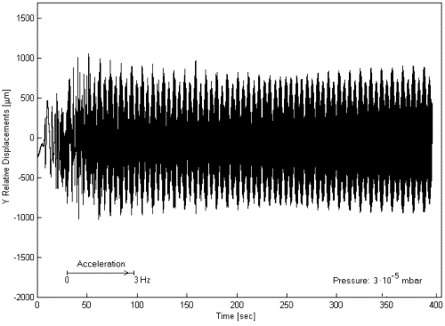
Fig. 8. Relative displacements (for the Y direction only, in the rotating reference frame) obtained with the same instrument as in Fig. 7 but having brought it to a rotation rate of 3 Hz. The natural differential oscillation at about 11 s period (the same as at zero spin) is apparent, as it is the faster rotation frequency of the system at 3 Hz.
Besides the natural frequency for differential oscillations the accelerometer system of
Fig. 2 has two additional natural frequencies, one slightly
below and one slightly above 1 Hz. The first can be viewed as the pendular frequency
(common mode) of the whole system; the second one as due to the inner test cylinder being
suspended close to its center of mass and having a non-zero moment of inertia with respect
to the symmetry axis (if the inner mass is modeled as a point mass this frequency
disappears). The predicted theoretical values of these natural frequencies have been
confirmed by experimental measurements. In order to reach the spin rates of interest
(above 1 Hz), the system must cross all these natural frequencies, and when passing the
two nearby ones it can undergo large resonant disturbances. It has been suggested (Luo, 2000)
that the system be simplified by substituting the laminar suspension of the inner test
cylinder (the bottom one of the three sketched in Fig. 2; see
also Fig. 4) with a solid brass cylinder of the same external
dimensions. By simple readjustments of arms and masses we have set up the system for
routine measurements with the natural period for differential oscillations close to 8 s
and the pendular frequency slightly below 1 Hz. These two values were predicted
theoretically and confirmed by measurements. Q measurements at variable residual
pressure in the vacuum chamber are reported in Section 5. It
is worth noting that in this arrangement the relevant whirl frequency of the test
cylinders is split into two: a forward one, increasing with the spin rate, instead of
remaining constant (as shown in Figs. 7 and 8) and a backward
one. The reason is the following. A differential force acting between the test cylinders
in their vertical beam balance arrangement causes a relative displacement of their centers
of mass by inclining the coupling arm of the balance pivoted at its midpoint. In this
case, if weakly suspended one at each end of the arm, the test cylinders keep spinning
around their axes. However, if the inner test cylinder is rigidly connected to the end of
the arm, the inclination of the arm forces it to spin along the arm itself, describing a
whirl cone, while the angular momentum of the body would tend to conserve its vertical
direction. The result is a stiffer or softer suspension of the inner test cylinder,
depending on the sense of rotation and![]() since the two are coupled
since the two are coupled![]() also a period of their whirl motions
shorter or longer than that of the natural oscillations, depending on whether whirl motion
is in the same sense as the rotation or in the opposite one (see Section
5). The whirl period relevant to the sensitivity of the accelerometer is the shorter
one, corresponding to a stiffer coupling.
also a period of their whirl motions
shorter or longer than that of the natural oscillations, depending on whether whirl motion
is in the same sense as the rotation or in the opposite one (see Section
5). The whirl period relevant to the sensitivity of the accelerometer is the shorter
one, corresponding to a stiffer coupling.
Spinning bodies are subject to gyroscopic effects, whereby they move not in the
direction of the applied force but along the component of the external torque
perpendicular to the spin axis. In a ground laboratory the gyroscopic effect for a body of
mass m, angular momentum ![]() and center of mass suspended
with an arm
and center of mass suspended
with an arm ![]() is due to the torque generated by the local gravity
and to the angular velocity
is due to the torque generated by the local gravity
and to the angular velocity ![]()
![]() of the
Earth's diurnal rotation around its axis:
of the
Earth's diurnal rotation around its axis:
(2)
Gravity makes the body precess around the local vertical (unless the center of mass lies exactly on the vertical itself), while the non-inertial nature of the laboratory reference frame (because of its diurnal rotation with the Earth) makes it precess around the Earth's rotation vector; the suspensions produce a restoring force towards the vertical. Equilibrium is reached in the North-South direction, the only direction along which the acting torques can balance each other. The test cylinders of Fig. 2 undergo different gyroscopic effects, resulting in a net relative displacement in the North-South direction. Its calculation shows a constant displacement at any given spin rate, and a linear increase with it, reaching several Ám at a few Hz; if the laminar suspension of the inner test cylinder is substituted by a rigid connection the differential gyroscopic effect increases by about a factor of 10 (see measurements of gyroscopic effect in Section 5). In both cases it is in the same direction as the effect of an EP violation in the gravitational field of the Earth, and much larger. Instead, a relative displacement due to an EP violation in the field of the Sun would show up as an additional vector following the daily motion of the Sun (the gyroscopic constant displacement can be subtracted away during data analysis or compensated by properly changing the verticality of the suspension shaft in the North-South direction).
For this reason the rotating differential accelerometer of Figs. 2 and 3 can be used as a prototype test instrument of the one proposed for space and for testing the equivalence principle in the field of the Sun, but cannot be used for testing the equivalence principle in the field of the Earth. It is worth stressing that the gyroscopic effect would not affect the space instrument ("GALILEO GALILEI" (GG), Phase A Report, 1998, Section 2.1.2). Unlike what happens in a ground laboratory, the angular momentum vector of the rotor is almost fixed in space, undergoing only a slow precession (around the orbit normal) due to the fact that the spin axis is not exactly normal to the orbit plane and the moment of inertia with respect to the spin axis is the dominant one ("GALILEO GALILEI" (GG), Phase A Report, 1998, Eq. (2.11)) (the effect is similar to the luni-solar precession of the Earth's axis around the normal to the ecliptic). The system is symmetrical and the test cylinders are suspended from their center of mass and symmetrically with respect to it (see Fig. 6). The resulting gyroscopic effects are found to be totally negligible ("GALILEO GALILEI" (GG), Phase A Report, 1998, Section 2.1.2; Comandi, 1999, Section 3.17).