2.1 Experimental Concept
2.1.1
Test Bodies, Expected Signal and PGB Laboratory
2.1.2 Implications on Spacecraft, Attitude and Orbit
2.1.3
The Read-Out System
2.1.4 Balancing
of the Test Bodies and Common Mode Rejection
2.1.5 Self-centering,
Whirl Motions and Stabilization
2.1.6 Locking/Unlocking
2.1.7 Calibration
Procedure
2.2 Perturbation Analysis, Requirements and Error Budget
2.2.1 Requirements on Drag Compensation and Balancing
2.2.2 Earth Tidal Perturbations
2.2.3 Radiometer Effects and Thermal Requirements
2.2.4 Electrostatic and Magnetic Effects
2.2.5 Coupling to Higher Mass Moments of the Test
Bodies
2.2.6 Requirements and Disturbances from Whirl Control
2.2.7 Thermal Noise and Error Budget
This Chapter Ready to Download and Print (1.8 MB): chapter_2.pdf
GG is an experiment in space to test the Equivalence Principle through a test of the so called Universality of Free Fall, namely that two bodies of different composition orbiting around the Earth should move with the same acceleration, hence along the same orbit. In order to eliminate major, purely classical, differential effects due to non uniformity of the gravity field of the Earth the test bodies are concentric hollow cylinders, as they were in the STEP project since its very beginning.
How an EP violation signal would affect the GG test bodies (in the
plane perpendicular to their spin/symmetry axis) is shown schematically in Fig. 1.1 where
most details have been omitted in order to show the essence of the experiment. The test
cylinders are weakly coupled by mechanical suspensions (not shown here; see Fig. 2.1); if
the Equivalence Principle is violated and one of the bodies is attracted by the Earth more
than the other, the two centers of mass reach equilibrium at a position displaced by ![]() (towards the center of the
Earth) where the new force is balanced by the restoring force of the suspension. For a
given value of the differential force (on one body with respect to the other) the weaker
is the suspension, the larger will be the displacement. Since our goal is to be sensitive
to extremely small differential forces in order to test the Equivalence Principle to
(towards the center of the
Earth) where the new force is balanced by the restoring force of the suspension. For a
given value of the differential force (on one body with respect to the other) the weaker
is the suspension, the larger will be the displacement. Since our goal is to be sensitive
to extremely small differential forces in order to test the Equivalence Principle to
High Frequency Signal Modulation. How can the signal caused by the
mechanical displacement ![]() be modulated at a
frequency higher than the orbital frequency? The mechanical displacement is transformed
into an electric potential signal by the capacitance read- out
whose plates are located in between the coaxial test cylinders. If the capacitance plates
spin at angular frequency w
be modulated at a
frequency higher than the orbital frequency? The mechanical displacement is transformed
into an electric potential signal by the capacitance read- out
whose plates are located in between the coaxial test cylinders. If the capacitance plates
spin at angular frequency w
![]() 2.1
2.1
wherefEP is the known phase of the EP violation signal (the displacement vector
Weak Mechanical Coupling of the Test Cylinders. In order to be sensitive to the differential force of an EP violation, as shown in Fig. 1.1, the GG test cylinders must be coupled mechanically, and very weakly. The way they are coupled is shown in Fig. 2.1. This Figure is to scale for the case of an inner hollow cylinder made of
Pt/Ir (21.56 g/cm3 density) and an outer one (much less dense) made of Be (1.848 g/cm3). Once the practicalities of manufacturing the test bodies have been taken into consideration, this material choice is a good one from the viewpoint of maximizing the effect of EP violation, because a new interaction is generally expected to couple to baryon number. A very large density difference is an important assembling constraint in the GG experiment design, as it is apparent in Fig. 2.1 because the room available is very limited. From the viewpoint of cost, a more realistic choice is for the inner test cylinder to be made of Cu rather than Pt/Ir (testing composition dependence with Be and Cu is a frequent choice in ground EP experiments) and this is our current baseline.Absence of weight in space allows the test bodies to be suspended with mechanical suspensions of extremely low stiffness (helical springs and flat elastic gimbals), which is ideal for detecting an EP violation effect to high accuracy because it makes the corresponding relative displacement between the test bodies appreciable by the capacitance read- out. In the current baseline and finite element simulation of GG (see Chap. 6) the helical springs and flat gimbals have stiffness, respectively,
k=10-2 N/m (10 dyn/cm) and ktor=4× 10⁻⁶ N× m (40 dyn× cm). Helical springs and gimbals with elastic properties close to these nominal values have been manufactured in CuBe by a small Italian company (DG Technology Service, Parma) (Figs. 2.2 and 2.3). The helical springs have been carved out of a single piece of CuBe by electroerosion in 3D with special equipment, followed by Brush- Wellman heat treatment and ultrasound cleaning. The flat gimbals are also made in CuBe by electroerosion, with the same heat treatment and ultrasound cleaning. This very careful manufacturing is required in order to obtain a good mechanical quality (high quality factor Q) of the suspensions of the test masses and to avoid the release of accumulated stress and consequent time varying elastic properties. A high Q is very important to reduce the thermal noise of the test bodies and also, in the GG rotating system, to decrease the growing times of whirl motions (see Sec. 2.1.5 for whirl motions and Q measurements).It is worth noticing that no electric signal goes through the helical springs; this avoids electric insulation of the springs (with plastic or glue) which would certainly impoverish their mechanical quality. The only electric connection from the PGB laboratory to the test bodies (needed for commanding the piezoelectric actuators) is through the flat gimbals, and this is possible without applying any insulation on the thin torsion wires of the gimbals, which again would reduce the mechanical quality. The flat gimbals have
6 wire sectors (see Fig. 2.3); each sector is connected to the inner clamping ring on one end and to the outer clamping ring on the other. Since 3 electric wires are sufficient, 3 of these 6 sectors are used in alternation, which means that they can be electrically insulated on the clamping rings, rather than on the thin wires themselves, thus avoiding negative effects on their mechanical quality.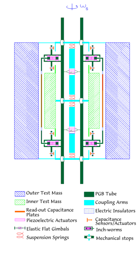
Figure 2.1 (to scale) Section through the spin axis of the GG test cylinders (10 kg each) and the capacitance plates of the read-out in between. The lower density cylinder (21 cm in height) encloses the higher density one. Inside the inner cylinder is a narrow tube rigidly connected to a laboratory (also of cylindrical shape) called PGB (Pico Gravity Box) enclosing the test bodies and the read-out capacitance plates shown here. The PGB in its turn is mechanically suspended inside the spacecraft (not shown; see Fig. 2.8 for an overall view). For coupling the test bodies there are two "coupling" arms (shown in light blue) located inside the PGB tube but not in contact with it; the inner test cylinder is suspended from the coupling arms at its center by means of two helical springs; the outer one is also suspended from the arms with helical springs, one at the top and one at the bottom of its symmetry axis. The only connection between the coupling arms and the PGB laboratory is via two flat gimbals at the midpoints of each arm. Being pivoted on torsion wires the gimbals allow conical movements of the coupling arms around their midpoints, e.g. in response to a differential force between the test bodies. The piezoelectric actuators shown next to the gimbals are for adjusting the length of the two halves of each coupling arm. The capacitance plates of the read- out are shown in between the test cylinders; they are connected to the PGB tube and have inch- worms for adjusting their distance from the surfaces of the test cylinders. On the PGB tube are shown the mechanical stops which constrain the test bodies to only slight movements. The small capacitance sensors/actuators (with plates of about 2 cm2) are for sensing and damping the slow whirl motions of the test bodies with respect to the PGB (see Sec. 2.1.5 and Chap. 6).
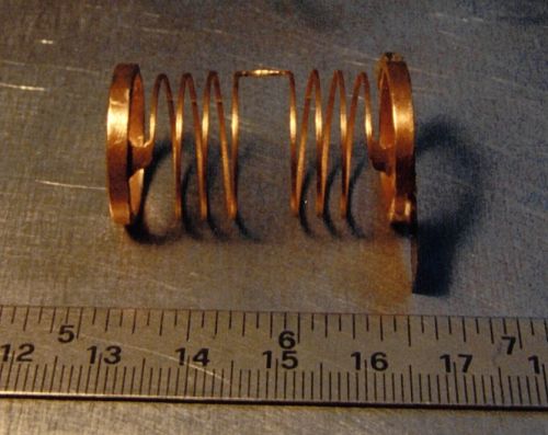
Figure 2.2 One of the 4 helical springs to be used for suspending the GG test bodies; two such springs are needed for each test body (as shown in Fig. 2.1). This spring has been manufactured in CuBe by DG Technology Service, Parma (Italy) according to our design. They have manufactured the spring by electroerosion in 3D from a single piece of CuBe with special equipment, and then have applied Brush-Wellman heat treatment and ultrasound cleaning. The elastic properties are close to the desired ones. Each spring is clamped by the thick rings at its ends. It is well known that most energy losses (which reduce the mechanical quality) occur at the clamping, no matter what clamping means are used - screws, welding, glue…; if clamping takes place far from where deformations occur during the oscillations (such as the thick rings in this case), this will reduce clamping losses significantly. Half turns of this spring are clockwise and the other half counter- clockwise; this is for de-coupling torsional from longitudinal (axial) oscillations.
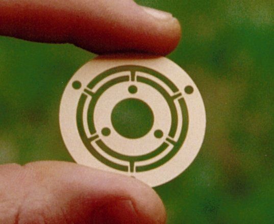
Figure 2.3 One of the two flat gimbals to be used for coupling the GG test bodies (as shown in Fig. 2.1). The outer ring is clamped to the PGB tube and the inner one to the coupling arm (in Fig. 2.1 the PGB tube is shown in dark green and the coupling arm in light blue). There are 6 wire sectors in between the clamping rings; 3 of them (in alternation) carry electric signals and are insulated at the clamping (on the outer and inner clamping rings); no electric insulation is needed on the thin wires themselves where deformations occur. The manufacturer of the gimbals is the same as for the helical spring; the same heat treatment and cleaning procedure have been applied.
The way each gimbal is mounted is shown schematically if Fig. 2.4, where it is apparent that it allows conical movements of the coupling arm at its midpoint. By commanding the piezoelectric actuators it is possible to change the relative axial position of the centers of mass of the test bodies, allowing axial centering; in addition, it is possible to change the length of the two halves of the arm, which is extremely important for balancing the test bodies under the effect of the residual drag (Sec. 2.1.4, Fig. 2.13). Note that, if inch-worms are used rather than ordinary piezo, it is possible to switch off the electric potential once the desired adjustment has been achieved; in this way they will not disturb the EP measurements nor produce joule heating inside the PGB (small force gravitational experiments should be as passive as possible).
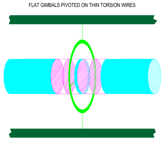
Figure 2.4 Schematic view of one flat gimbal pivoted on torsion wires. The inner ring of the gimbal is clamped on the coupling arm (in light blue) and the outer one on the PGB tube (of which only a section is shown). The length of the two halves of the arm can be changed by means of the piezoelectric actuators (schematized by their end faces). Torsion of the wires allows conical movements of the coupling arm at its midpoint.
Low Noise Suspended Laboratory (PGB). As shown in Fig. 2.1 that the only connection between the (coupled) test bodies and the "outside world" is through the flat gimbals. It is very important for such a connection not to be directly to the spacecraft, but through an intermediate stage, in its turn suspended from the spacecraft. This intermediate stage is a cylindrical laboratory whose mechanical suspension from the spacecraft (also a very weak suspension, as it is possible in space), provides an effective, passive (i.e. at essentially no cost) vibration isolation above its natural frequency of oscillation. This laboratory is shown in Fig. 2.8 under the name of PGB (Pico Gravity Box), from the original name given to a passive noise attenuator of this kind to be used for low gravity experiments, typically in a box of available volume, on board the space station (Nobili et al., 1991, Catastini et al., 1992).
The PGB laboratory shown in Fig. 2.8 is suspended from the spacecraft with
2 helical springs, one of which is shown in Fig. 2.5. It is made of 1 steel wire of 0.15 mm diameter, which provides the stiffness, and Cu wires (0.12 mm diameter each) for the required electric connections from the spacecraft to the laboratory (3 in this spring; 6 are needed in the GG experiment, 3 through each PGB spring); each Cu wire has a resistance of 1.5 W and is insulated to better than 20 MW . All wires are glued with epoxy and made into a helical spring as shown in the picture with elastic properties (both in the longitudinal and the transversal direction) very close to the nominal ones in the current GG baseline, namely 10-2 N/m (10 dyn/cm). This is easily obtained by playing with the parameters which determine the elastic properties of helical springs, namely the thickness of the wire, the number of turns, the diameter of each turn, the total length of the wire (45 cm in this case). Although this spring is very soft, two of them can very well suspend the PGB laboratory and the test bodies apparatus inside it, all together a mass of several tens of kg. This is because, in absence of weight, the largest force that the GG spacecraft is subject to is due to air drag, which is about 108 times smaller than 1-g on Earth. The largest deformation that the PGB springs will undergo, before drag compensation, is very minute compared to their length and size (less than 0.7 mm); there is certainly no danger to overcome their elasticity regime.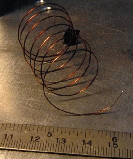
Figure 2.5 One suspension spring of the PGB laboratory
In GG an EP violation signal is modulated at the spin frequency of the sensors. Vibration noise at this frequency (or close to it), i.e. noise which acts at
2 Hz with respect to the Earth, hence at 4 Hz or DC in the rotating frame, is effectively attenuated by the mechanical suspensions of the PGB laboratory inside which the experiment is carried out. As seen in the fixed frame, the system is transparent to DC and low frequency effects (like the signal, the residual atmospheric drag and its low frequency fluctuations...) but is very efficient in attenuating vibration noise above its threshold frequency, particularly around the spin frequency. The transfer function of the system, when viewed in the rotating frame, shows a sharp peak of value 1 at 2 Hz (Fig. 2.6), meaning that the system is perfectly transparent at the signal frequency (see Catastini et al., 1996 for details). In this way the signal is not affected, in amplitude, by the spin; also the low frequency drag effects (of the fixed frame) are up-converted to high frequency with no amplification (and no reduction either, of course). The only difference, and indeed big advantage, with respect to the non rotating case being that the detecting instruments work much better at higher frequency. So the sharp peak at 2 Hz is a key feature of GG. But how can the peak at 2 Hz be so sharp? Simply thanks to the fact that the PGB provides good attenuation at its sides, at lower and higher frequencies, i.e. around 4 Hz and 0 Hz (w.r.t the rotating frame). This means good attenuation of perturbations which are at 2 Hz w.r.t the fixed frame. The need to attenuate these perturbations should not be neglected. Although in space a motor is obviously not needed, we cannot forget that the FEEP thrusters will act at about 2 Hz (to reduce the main along track effect of drag at the orbit frequency, and also its low frequency components). Since the FEEP thrusters compensate low frequency drag effects while spinning at 2 Hz, any mismatches and imperfections in their firing will give rise to spacecraft perturbations at 2 Hz w.r.t. the fixed frame (hence at 4 Hz and 0 Hz in the rotating frame). Sonic noise of the GG spacecraft structure will be peaked at much higher frequency, but a tail at the spin/signal modulation frequency should not be excluded, and will be attenuated.The transfer function of the rotating PGB for a quality factor
Q of the suspensions of 90 and 400 is shown in Fig. 2.6, in the non-rotating frame (upper plot) and in the rotating one (lower plot). Q=90 is the value measured in the laboratory for the PGB spring shown in Fig. 2.5 (see Q measurements in Sec. 2.1.5). This low Q value of the PGB springs (as compared to the Q of the springs which suspend the test bodies) is due to the fact that the PGB springs have to carry wires and their insulation. A Q value higher than this, e.g. Q=400, can be easily obtained by manufacturing the PGB helical springs with separate wires insulated at the clamping; these will have a lower dissipation and therefore a higher Q.In summary, the weak mechanical suspensions of the PGB - which can be used only thanks to weightlessness- provide an effective, passive means of isolation from the (relatively) high frequency vibrations around the spin/signal modulation frequency; in addition, they provide electric grounding (see Sec. 2.2.4) and make the PGB laboratory essentially thermally de-coupled from the spacecraft (see Sects. 5.4 and 4.4). All of these are very important advantages for the purpose of achieving a high accuracy test of the Equivalence Principle.
Amplitude of the Expected Signal. In the GG numerical simulation (see Sec. 6.1.10), with the nominal elastic properties of the suspensions given above (and close to those of the suspensions in
CuBe shown in Figs. 2.2 and 2.3) the natural frequency for differential oscillations of the test bodies (differential mode) is w dm @ 1.15× 10⁻² rad/sec, corresponding to a natural period of about 545 sec (Table 6.4). The resulting amplitude of the relative displacement of the test bodies in response to an EP violation to the level h =10-17 (current target of GG) - yielding an acceleration signal![]() (2.2)
(2.2)
modulated at the spin frequency according to Eq. (2.1). As a mechanical displacement, D
xEP @ 6.3× 10⁻³ Å is incredibly small; however, once it has been transformed into an electric potential signal via a relative change of capacitance in the read-out capacitance bridge, it can be detected, as we have verified experimentally (see Sec. 2.1.3 and Chap. 3). It is clear, however, that the very weak mechanical coupling of the test bodies achievable in space (a natural differential period of 520 sec is very long, meaning that the coupling is very weak indeed) is crucial in order to get a displacement value within the reach of a capacitance read- out.Finally, as mentioned in Sec. 1.4, mechanical suspensions allow electric grounding of the test bodies and eliminate the major effects of electric charging. There are no floating bodies in GG, as it is shown in Fig. 2.8.
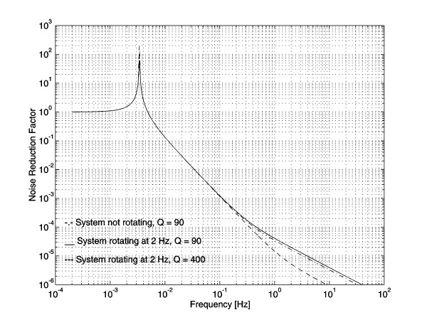
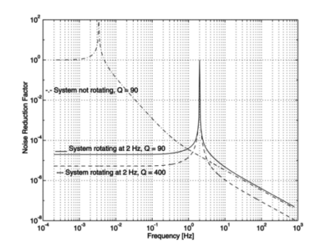
Figure 2.6 Transfer function of the GG Spacecraft/ PGB system as seen in the non rotating frame (upper figure) and in the frame rotating at 2 Hz (lower figure) together with the whole system. The noise reduction factor plotted on the vertical axis is the ratio: amplitude of disturbing vibration at the PGB level to amplitude of vibration at the GG spacecraft level. The lower this ratio, the lower the platform noise of the experiment, since the experiment is carried out inside the PGB. We consider the two cases Q=90 (currently measured) and Q=400 (readily achievable). In both figures we plot also the transfer function in the zero-spin case (i.e. PGB suspended inside the spacecraft with the system not spinning) to recover the familiar shape of the transfer function, with noise attenuation above the natural oscillation frequency of the system and the resonance peak; the peak height is low for a finite, low, Q. As viewed in the non rotating system (top), the transfer function is not changed very much by the spin because it depends on the elastic properties of the suspensions, and rotation does not bring in any dramatic changes (deformations are minute). It is apparent that the system is transparent to frequencies lower than the natural frequency of the system, such as the orbital frequency while it provides good attenuation close to the spinning frequency (the modulation frequency of the EP violation signal). When viewed in the rotating frame (bottom) there is a peak with value 1 at the spinning frequency, showing that vibrations at very low frequency w.r.t. the fixed frame, particularly the DC ones, are not attenuated; the observer co-rotating with the system sees these DC perturbations as 2 Hz, and finds that the suspension does not reduce them, namely that it is transparent to 2 Hz effects. Perturbations which are seen at 2 Hz by the non rotating observer (and attenuated), have frequencies 0 and 4 Hz for the rotating one, and in fact he too finds that they are attenuated.
Alternative Weak Coupling Design. Although helical springs and flat gimbals have many advantages and allow to weakly couple the GG test cylinders as it is required for high accuracy EP testing, they are not the only solution. An alternative design to the one shown in Fig. 2.1 and discussed above, is shown in Fig. 2.7, based on thin, curved laminar suspension strips to be manufactured from a CuBe foil in the required curved shape shown in the figure (they should not be bent elastically) so as to avoid release of accumulated stress. The advantage of this design is to be more sensitive to differential forces and stiffer in common mode. The laminar suspensions should also be easier to manufacture and handle.
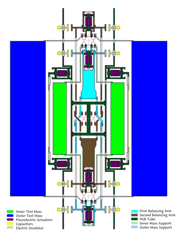
Figure. 2.7 Alternative design, with respect to the baseline one shown in Fig. 2.1, for a weak coupled suspension of the GG test cylinders; section through the spin/symmetry axis. The two balancing arms are twice as long as in Fig. 2.1, which increases the sensitivity by a factor of 4. The bodies are coupled by thin, curved laminar suspension strips; there are 3 of them at each level, symmetrically placed around the axis (there can be more, but always symmetric). The particular geometry of mounting them ensures that the pivoting points of the two balancing arms are well defined and that those at the center of the rotor coincide well one with the other (at the cross shown). These suspensions are very soft for lateral differential oscillations of the two test masses and at the same time are particularly rigid for unwanted motions, like common mode lateral oscillations and rotational oscillations around the spin axis. They have enlarged ends for clamping (so as not to add dissipation at the clamps), and those in the central part of the rotor are fastened by electrically insulating clamps, so that these suspensions can be used as conducting leads between the PGB tube and the two balancing arms for the driving voltages of the four axial inch-worms, which are used for balancing the two rods and for adjusting the axial position of the two test masses. Once the desired balancing has been achieved the driving voltages of the inch-worms are switched off, leaving them blocked; in this way they will not disturb the EP measurements nor produce joule heating inside the PGB laboratory. The small capacitance sensors/actuators for sensing and damping the whirl motions, and the capacitance plates of the read-out are shown, as in Fig. 2.1.
2.1.2 Implications on Spacecraft, Attitude and Orbit
Need for a Spin Stabilized Spacecraft in Low Earth Orbit. The test bodies, their mechanical coupling and the capacitance read-out are the core of the GG mission. Once the experimental design outlined in the previous section has been conceived, the features of the required spacecraft, its attitude and orbit are also identified. In the first place, the cylindrical symmetry of test bodies and PGB and the request to spin, suggest a spacecraft of cylindrical symmetry too, stabilized by one-axis rotation along the symmetry axis. The nature of the signal (see Fig. 1.1 and Eq. 2.1) requires the spin axis to be as close as possible to the orbit normal; the need to reduce non gravitational perturbations on the spacecraft surface (Sec. 2.2.1) suggest that it should be small and compact (which in addition helps reducing its cost); the need to reduce perturbations on the test bodies from nearby moving masses suggests to use thrusters of high specific impulse (such as FEEP; see Sec. 4.2) in order to reduce the amount of propellant required for drag compensation during the mission.
A section of the GG satellite through its spin/symmetry axis showing how the PGB and the experimental apparatus is accommodated, in a nested arrangement inside it, is shown in Fig. 2.8; a 3-D view is given in Fig. 2.9 (see Chap. 5 for details). The spacecraft is 1 m wide and 1.3 m high. The area of the external (cylindrical) surfaces covered by solar cells is dictated by the power needs of the mission (somewhat more than 100 W); the compactness of the spacecraft (similar to a spinning top in shape) is for maximizing the moment of inertia with respect to the symmetry axis whereby providing passive spin stabilization around it. The current nominal spin rate is 2 Hz (120 rpm), yielding a peripheral acceleration of about 8 g, which is well doable. From the viewpoint of the EP experiment the modulation frequency of the signal, hence the frequency of spin, should be as high as possible: the higher the better, to reduce mechanical noise and low frequency "1/f" electric noise. In addition, a higher spin rate, with very weak suspensions at it is possible to use in space, makes the test bodies closer to being free, ideal rotors (see Sec. 2.1.5), which is advantageous for the EP experiment. However, there are practical constraints which is better not to push to their limits in order to reduce the complexity and cost of the spacecraft. A spin frequency of 5 Hz, with spacecraft dimensions close to the current ones, was the original choice for GG (Nobili et al., 1993; Nobili et al., 1995). The current baseline is safer and poses no problems. Indeed, the first Italian satellite, Sirio, flown more than 20 years ago, was very similar to GG: cylindrical in shape, passively stabilized by one axis rotation, with mass, spin rate and maximum peripheral acceleration very close to those of GG. In any case, a spin frequency of 2 Hz already provides a modulation of the expected EP signal about 104 times higher than ever achieved.
From Eq. (1.2), which gives the intensity of the expected signal acceleration for an EP violation expressed by the adimensional Eötvös parameter h , it is apparent that the lower is the orbiting altitude the stronger is the signal. The altitude h of the satellite orbit is chosen having in mind two competing needs. On one side there is the need for an orbit altitude as low as possible, as this increases the strength of the signal; however Eq. (1.2) shows that the dependence on h of the acceleration signal is very slow for low Earth satellites (RÅ >>h). On the other hand, the altitude should be high in order to reduce the relevant disturbing effect from the residual atmosphere, at least as long as this becomes comparable to the effect of solar radiation pressure, which cannot be avoided anyway. The value of h is much more relevant for air drag acceleration than it is for the strength of the signal, because of its linear dependence on air density. In the current baseline we have h @ 520 km. It is worth noticing that in the case of GG the only concern about a higher altitude is for a slightly weaker signal; there is no special concern on charged particle effects (as it is the case in STEP) because there are no relevant electrostatic effects (Sec. 2.2.4).
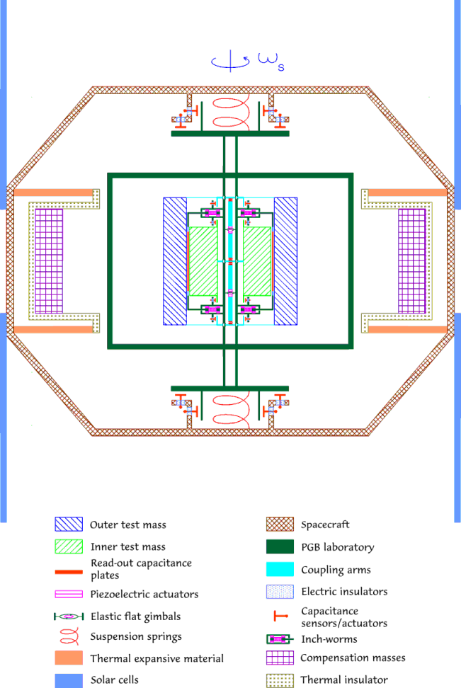
Figure 2.8 Section through the spin axis of the GG satellite. The solar panels are shown, in two cylindrical halves at the two ends of a girdle which is the central part of a very compact spacecraft of cylindrical symmetry, resembling a spinning top, - made of the central girdle, one truncated cone above and one below- all to be manufactured in carbon fiber composite (see Fig. 2.9 for a 3-D view of the GG spacecraft with and without the solar panels). Inside the spacecraft is shown the PGB laboratory with its helical suspension springs and small capacitors for sensing its relative position with respect to the spacecraft, both along the symmetry axis and in the transverse plane. The rôle of the passive compensation masses is discussed in the Section and shown in Fig. 5.7. A blow up of the cylindrical test bodies and the read-out sensors located inside the PGB is shown in Fig. 2.1
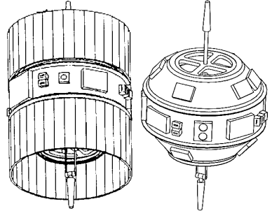
Figure 2.9 The GG spacecraft with solar panels (left) and without (right), showing its compact "spinning top"- like shape The outermost cylinder is 1 m wide and 1.3 m high. On the central girdle are located some electronic boxes, the Earth/Sun Sensors and the FEEP thrusters. One of the two antennas can be folded to reduce the required fairing space at launch.
Why an Equatorial Orbit. Due to the flattening of the Earth any
satellite orbit whose inclination I over the equator is
different from exactly 0 or p /2 is subject to the regression of its line of nodes. The dominant
effect on the longitude W of the ascending node of the
satellite orbit is due to the zonal harmonic ![]() of the gravity field of the Earth (which expresses its polar flattening) with a rate of
change:
of the gravity field of the Earth (which expresses its polar flattening) with a rate of
change:
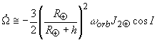 (2.3)
(2.3)
where w orb
is the orbital angular velocity of the satellite at altitude h around the Earth. The
formula is valid for small values of the orbital eccentricity e
(e2 terms neglected) and non-zero inclination (for
symmetry reasons, there is no such effect at I =
0); there is either regression or advance of the line of nodes depending on
whether I is smaller or bigger than 90° ; there is no motion of the nodes for an exactly polar
orbit (I = p /2).
For any inclination 0 < I < p /2, assuming the spin axis unit vector of the satellite ![]() to be
initially parallel to the orbit normal
to be
initially parallel to the orbit normal ![]() (and neglecting at this point all
perturbations on
(and neglecting at this point all
perturbations on ![]() (see below) the two vectors will be an angle 2I away from one another after a time
(see below) the two vectors will be an angle 2I away from one another after a time ![]() i.e. after half period of
the regression of the nodes (see Fig.2.10). For low orbit altitude and inclinations of 5 to 20 degrees
half the period of the nodes is from 25 days to about 1 month, to be compared with a mission duration of 7
months, which means that the higher the orbit inclination the more important
would be - in order not to loose in signal strength- to perform attitude maneuvers so as to keep the spin axis close to
the orbit normal. No such maneuvers are needed at inclination close to zero, and this is
why an equatorial orbit is preferable. An orbit very close to a polar one would also be
suitable from this point of view; however, it would offer no major advantages from the
viewpoint of launch while it is certainly less advantageous for ground operation from the
Italian equatorial station of Malindi. Although GG is a mission far from heavy on data
rate (see Chap. 7) its operation if close to equatorial orbit is definitely easier for the
Italian ground station.
i.e. after half period of
the regression of the nodes (see Fig.2.10). For low orbit altitude and inclinations of 5 to 20 degrees
half the period of the nodes is from 25 days to about 1 month, to be compared with a mission duration of 7
months, which means that the higher the orbit inclination the more important
would be - in order not to loose in signal strength- to perform attitude maneuvers so as to keep the spin axis close to
the orbit normal. No such maneuvers are needed at inclination close to zero, and this is
why an equatorial orbit is preferable. An orbit very close to a polar one would also be
suitable from this point of view; however, it would offer no major advantages from the
viewpoint of launch while it is certainly less advantageous for ground operation from the
Italian equatorial station of Malindi. Although GG is a mission far from heavy on data
rate (see Chap. 7) its operation if close to equatorial orbit is definitely easier for the
Italian ground station.
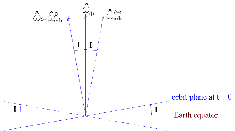
Figure 2.10 The figure shows the relative
position of three unit vectors: the spin axis of the Earth ![]() , the spin axis of the GG satellite
, the spin axis of the GG satellite ![]() (both fixed in time) and the normal to the orbit plane of GG
(both fixed in time) and the normal to the orbit plane of GG ![]() for a given orbital inclination I . The orbit normal is drawn in two positions: at initial time, as
for a given orbital inclination I . The orbit normal is drawn in two positions: at initial time, as ![]() assuming that it coincides with
assuming that it coincides with ![]() and after
and after
The price to pay for this choice is to deal with severe thermal variations due to the satellite coming in and out of the shadow of the Earth every orbit. And to be without sun power for a significant fraction of the orbital period. The only orbit which would solve (yet not totally) this problem is sun-synchronous, which however cannot (by definition) have zero motion of the node line (since its orbital plane is meant to follow the Sun) and is therefore incompatible with the GG need for a spin axis close to the orbit normal during the entire mission and no attitude maneuvers. However, we have found (see Sects. 4.4 and 4.5) that the GG thermal problems can be solved, thanks to the fast spin of the spacecraft and good vacuum inside it, using, in addition, passive insulation and a spacecraft structure in carbon fiber composite (with very low thermal expansion coefficient). The required thermal stability can be met by purely passive means.
A circular orbit is preferable, but a small eccentricity can be accepted in order not to put stringent requirements on the performance of the launcher. Residual eccentricity from the launcher can be as low as 0.01, a value which is acceptable for GG. An orbit inclination of no more than 0.2° is within the current launcher performances; as for having the spin axis close to the orbit normal, active maneuvers can be performed (before spin up to the nominal rate) reaching a deviation <1° . Apart from the regression of the line of nodes, and its consequences on the strength of the EP signal, perturbations on the GG orbit do not have any relevant consequences over the 7 months nominal duration of the mission. The pericenter will precess; the orbit will circularize and spiral in due to air drag; orbital effects of radiation pressure in semimajor axis will average out every orbit (Milani et al. 1987, Chap. 4). All these non gravitational effects are significantly reduced by FEEP drag compensation; in any case, none of them is of any concern for of the experiment and the mission. No precise satellite tracking is required; tracking with an ordinary accuracy of several km along track is sufficient for the purposes of the EP experiment.
Passive Compensation of Differential Rotation. With this choice of the orbit (almost equatorial, almost circular with the spin axis close to the orbit normal) there is an effect induced by eclipses which gives rise to an angular phase lag between the spacecraft outer shell and the payload suspended inside it, and it must therefore be taken care of (Lund, 1995).
The spin rate w os of the outer shell will change if the moment of inertia of the shell changes while the spin angular momentum remains constant. This indeed happens every orbit due to temperature variations of the outer shell as the GG satellite gets in and out of the Earth shadow, which is not the case for the PGB laboratory since it is very well insulated and thermally de-coupled from the spacecraft (see Sects. 4.4 and 5.4). Hence, a differential rotation rate of the outer shell with respect to the PGB is to be expected. The relative change of the angular velocity of the outer shell w os with respect to its nominal spin angular velocity w s must equal the relative change of its moment of inertia Jz with respect to the symmetry/spin axis (due to the conservation of spin angular momentum), and it must be:
![]() (2.4)
(2.4)
where a os is the thermal expansion coefficient of the outer shell and D T its temperature variation due to the eclipse. Because of the low torsion constant of the PGB springs the natural period for torsion oscillations of the spacecraft/PGB systems is longer than the eclipse duration (about 1/3 of the orbit period); as a consequence, a differential rotation rate will accumulate over the eclipse passage, yielding a corresponding phase lag between the two bodies. We shall have:
![]() (2.5)
(2.5)
for the variation of the spin angular velocity in 1 eclipse passage of duration t eclipse, and a corresponding phase lag:
![]() (2.6)
(2.6)
The GG thermal model gives D T @ 30 degrees for the temperature variation of the spacecraft in 1 eclipse passage; if the spacecraft is made of carbon fiber composite it is reasonable to have a thermal expansion coefficient a os @ 0.9× 10⁻⁶/K; thus:
![]() (2.7)
(2.7)
This result has been confirmed by detailed theoretical and numerical analysis; it is clearly unacceptable and calls for a solution. A way to solving it comes from noticing that such a large phase lag is due to the high spin rate of the spacecraft (together with the fact that the phase difference grows quadratically in time) while the absolute change in the moment of inertia is indeed very small. This means that it can be balanced by a small compensation mass. Moreover, compensation can be passive (Marchal, 1996); the idea is to have a mass which expands and contracts in anti-phase with respect to the outer shell of the spacecraft so as to keep the total moment of inertia (of the outer shell plus the compensation mass) essentially constant. Since the compensation mass should be small compared to the mass of the outer shell, clearly its expansion coefficient must be larger than the expansion coefficient of the outer shell (if the masses have about the same distance from the spin axis). Expansion is required in the radial direction (normal to the spin axis) because this is how the outer shell expands and contracts. Hence, there must be bars located radially from the cylindrical surface towards the spin axis, while the bulk of the compensation mass should be as close as possible to the outer shell in order to give the highest contribution to the total moment of inertia (and thus to its variations as well). Also, materials with high expansion coefficients tend to have low density. From all this we are led to the design shown in Fig. 2.8: a number of bar shaped supports with large thermal expansion coefficient a bar are located radially from the outer shell surface (in thermal contact with it) towards the spin axis; from the other ends, getting back towards the surface of the spacecraft, there are thermal insulating low expansion bars at whose ends the compensation masses are attached. As the spacecraft outer shell expands outward the compensation masses are displaced inward, and viceversa. The compensation masses are far away from the spin axis thus giving a large contribution to the moment of inertia. Care should be taken in maintaining symmetry in azimuth as well as top/down. Also, thermal insulation of the top radial bars and insulating masses is necessary not to bring heat inside. Three possible mass compensation designs are shown in Fig. 5.7. For the total moment of inertia to remain constant the ratio of the thermal expansion coefficients and the ratio of the moments of inertia (with respect to the spin axis) must satisfy the equation:
![]() (2.8)
(2.8)
and, with the design outlined above:
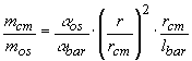 (2.9)
(2.9)
with mcm the total compensation mass (with bars of negligible mass), mos and r the mass and radius of the outer shell, rcm the radial distance of the compensation mass from the spin axis, lbar the length of the high thermal expansion bar. Using materials with a bar a factor 50 to 100 times larger than the expansion coefficient of the outer shell in carbon fiber it is found that a compensation mass not larger than 5 kg is sufficient. Note that a small compensation mass, and a small mass for the bar, i.e. a small mass for the entire system means that heat can be transferred (hence expansion/contraction achieved to compensate for those of the spacecraft) in a very short time.
How rapidly must this passive mass compensation system work in order to
keep the phase lag between the outer shell and the PGB within a required phase difference ![]() (namely, 1/10 of
the of angle available by the mechanical stops)? Assuming the temperature change to be
linear in time we get a quadratic growth of the phase lag angle with acceleration:
(namely, 1/10 of
the of angle available by the mechanical stops)? Assuming the temperature change to be
linear in time we get a quadratic growth of the phase lag angle with acceleration:
![]() (2.10)
(2.10)
giving about 240 sec for the response of the compensation system. Materials with thermal expansion coefficient as large as 10-4/K to be used for manufacturing the bars tend to have low thermal conductivity; they can have a thermally conductive inner bar so as to increase the surface of thermal contact with the expanding/contracting outer shell of the spacecraft thus reducing the response time. In any case there is sufficient time available. Instead, it is possible to use bars is special Al alloy which have somewhat smaller thermal expansion coefficient but high thermal conductivity and need no inner bar. The gravitational perturbation on the test bodies of all the moving mass (from the outer shell as well as the compensation mass) has been estimated and found not to be a problem (Sec. 2.2.5).
In the conservative assumption that 10% of (2.10) is not compensated passively, for the residual angular acceleration between the spacecraft and the PGB (3.4× 10⁻⁸ rad/sec2) the response time is 770 sec; it can be sensed and corrected. It is sensed by placing a small mirror on the PGB tube and a photo-detector on the spacecraft (it adds no wire to the PGB); the angular resolution (À 0.01 rad) is certainly not a demanding one. The photo-detector can then drive the FEEP thrusters to correct for the phase lag by spinning the outer shell up or down as necessary. The torque to be provided is of 10 m N× m, well within the capabilities of the thruster authority of the FEEP. Indeed, the FEEP could correct for the entire effect (no passive mass compensation), since this requires 100 m N× m, but it is preferable to limit the FEEP to fine adjustments only in order to reduce power consumption.
No such phase lags as those discussed above will take place between the PGB and the test bodies because of the very good thermal insulation (see Sec. 4.4); spring coupling will take care of eliminating residual small phase lags (e.g. left out by the unlocking procedure) within 2 weeks (see Sec. 2.1.6).
Effects on the Spin Axis. We have analyzed the effects of the regression of the nodes on the relative angle between the orbit normal and the spin axis, assuming the latter fixed in space. Although the approximation is correct, the spin axis is not exactly fixed in space. This is because a body with different moments of inertia (the GG satellite) whose spin axis is not exactly normal to the orbit plane will be forced to precess about the orbit normal by the monopole gravitational attraction of the central body (the Earth). The effect is similar to the well known luni-solar precession (with 26,000 yr precession period) of the spin axis of the Earth about the normal to the ecliptic produced by the monopole of the Moon and the Sun on a planet Earth which has a non zero quadrupole moment.
For an axisymmetric body having moments of inertia Jz with respect to the symmetry axis and Jx with respect to any axis in the transversal plane (Jz>Jx), whose spin axis - assumed to be coincident with the symmetry axis at this point- is at an angle q with respect to the orbit normal, it can be shown that the spin axis will precess about the orbit normal with a precession period Ppr given by (e.g. Afonso et al., 1989):
 (2.11)
This formula has been obtained after averaging over the fast variables, both the true anomaly and the longitude of the node. Clearly, the more the body differs from a sphere i.e. the larger is its fractional difference in the principal moments of inertia (Jz-Jx)/Jz, the more relevant this effect will be (i.e. faster precession). Once all the bodies have been unlocked, since they are weakly coupled and have different values for the fractional difference in the principal moments of inertia (Jz-Jx)/Jz they will precess at different rates, slower the test masses than the outer shell and the PGB (the test masses are manufactured with lower quadrupole moments). The fastest precession rate is that of the outer spacecraft, whose precession period amounts to Ppr @ 6 yr. (and it is the shortest of all). This means that the assumption made for the longitude of the nodes to be a fast variable too was indeed correct. Note that the precession angular velocities are different for the different bodies due to their different quadrupole moments, but they have all the same sign (in fact opposite to the sign of the spin angular velocity, which is obviously the same). The precession rate of the PGB is slightly slower than that of the outer shell, while those of the test bodies are at least a factor of ten slower. Let us consider the worst possible case: that of one body precessing at the fastest rate (i.e. the spacecraft outer shell) and another body with zero precession rate. In a given time interval D t the precession angle a pr covered by the vertex of the spin axis of the spacecraft in its precessional motion in the sky is a pr = (2p /Ppr)× D t. However, the spin axis is sweeping a precession cone of semi-aperture q , and therefore the angular displacement with respect to its original position (also the position of any axis not affected, or much less affected by this torque) is F =a prq (all angles in radians). Taking the entire 7 months nominal duration of the mission as D t, we get 9× 10⁻³ rad (0.6° ) for the total angular displacement. This value, which is an upper limit, is also much smaller (about 1/10) of the maximum physical room allowed by the mechanical stops for relative angular movements (in all degrees of freedom) for the suspended bodies.
However, in the above reasoning we have ignored the mechanical coupling between the two bodies. Instead, there are coupling springs which will be elastically deformed in response to the external torque until an equilibrium position is reached. The effect is like the so called "gyroscopic effect" for rotors on Earth - in the case that the coupled rotors be suspended by their center of mass- , noticing that on the ground precession would be around the diurnal angular velocity vector of the Earth, hence yielding a much stronger effect. The problem arises for the GG prototype experiment in the laboratory and it has been carefully investigated: the resulting angular displacement at equilibrium between the spin axes is very small even on Earth (10-5 rad or smaller depending on the arrangement; Comandi, 1998). It will be certainly smaller in space. Even more important, the GG test bodies in space are suspended from the center of mass (or symmetrically with respect to it): as a consequence, gyroscopic effects - in addition to causing very small angular displacements- will not affect the centers of mass of the test cylinders whose relative displacement is the only physical quantity relevant for the EP experiment.
The outer shell of the GG satellite is subject also to a number of non gravitational perturbations that can change its spin axis while not affecting the PGB laboratory and test masses suspended inside. As a result, there will be tilts which, although not affecting the centers of mass, may be unacceptable for the EP experiment. If so one should resort to active control of the spin, that is, GG should rely on compensation (to some extent) of non gravitational effects also in angle. From the analysis reported below we conclude that no active control is needed on the direction of the spin axis.
The main non gravitational torques are due to solar radiation pressure and air drag. Radiation pressure on the GG top and bottom covers is usually asymmetrical. The Sun is not always at zero declination over the equator of the Earth, the orbit of GG is not exactly equatorial, the spin axis is not exactly normal to it. So one cover is illuminated while the other is in the dark. The reflected part of this asymmetrical radiation gives a force along the spin axis, hence no tilt. Instead, the effect due the absorbed fraction has the same direction as the surface-to-Sun direction, and this has a component perpendicular to the spin axis which, in the case of asymmetrical illumination, results in a torque that can tilt the spin axis of the outer shell with respect to that of the PGB inside. The radiation pressure force on a GG cover can be estimated to be:
![]() (2.12)
(2.12)
where F sun is the solar flux, c the speed of light, r the radius of the GG spacecraft, d the declination of the Sun over the equator of the Earth and a ab the absorption coefficient of the surface. The corresponding torque is:
![]() (2.13)
(2.13)
where h is the height of the GG outer
shell. In the unfavorable, simplifying assumptions that d is
always at its maximum, that no shadowing occurs, and with a large value for a ab (0< a
ab<1) the maximum value of Nrp
is only of few 10-7 N× m,
to be compared with the enormous spin energy of the spacecraft, Espin=
Jzw s2 @ 5× 10³ N× m (a
factor at least 1010 bigger). As far as air drag,
is concerned, since the GG spacecraft is highly symmetric only fluctuations in the
residual (at the orbiting altitude) atmospheric density can give rise to a tilting torque.
Furthermore, only a fraction of such fluctuations will produce a tilting torque always in
the same direction. In the very conservative assumption that fluctuations producing a
tilting torque always in the same direction amount to 0.01 of
the average air density, the resulting torque would still be of the same order as in the
torque due to solar radiation estimated above; hence, also negligible compared to the spin
energy. For completeness we have estimated also the effect of a magnetic torque. Any
electric charge that were to materialize inside the spacecraft (e.g. interaction with
cosmic rays) will move to the external surface of its outermost conducting structure
because all parts are connected via conducting suspensions and there are no free floating
masses. Since GG is spinning this charge will create a current loop whose magnetic moment ![]() (parallel to the spin vector of the spacecraft)
will interact with the dipole magnetic field of the Earth
(parallel to the spin vector of the spacecraft)
will interact with the dipole magnetic field of the Earth ![]() giving rise to a torque
giving rise to a torque ![]() As a result, the spin axis will precess around
As a result, the spin axis will precess around ![]() . With an upper limit for the electric charge obtained from
charging on LAGEOS (an upper limit, because LAGEOS orbits in the middle of the Van Allen
belts) this magnetic torque turns out to be totally negligible.
. With an upper limit for the electric charge obtained from
charging on LAGEOS (an upper limit, because LAGEOS orbits in the middle of the Van Allen
belts) this magnetic torque turns out to be totally negligible.
Having analyzed all non gravitational perturbing torques (that we are aware of) which can tilt the spin axis of the GG spacecraft outer shell with respect to the PGB laboratory inside, we conclude that their effects are negligible by far and that no active control of the direction of the spin axis in space is needed. Such direction is absolutely stable. The simple physical reason behind this fact is that the kinetic energy of spin once at the nominal rate of 2 Hz is so high compared to all perturbing torques that they would need a very long time to even slightly displace the spin axis; with the addition of the restoring coupling of the springs, these torques are of no concern at all. From the viewpoint of satellite operation, this result is a very important simplification; in addition, a reduced complexity of the spacecraft is clearly beneficial for the experiment. By comparison, the STEP attitude needs to be actively controlled; moreover, it must be drag free also in angle to very high accuracy.
Besides the precessions caused by external torques (of both gravitational and non gravitational origin) there is a precession, known as Eulerian or free precession, and also as Eulerian or free nutation, which takes place in the absence of any external torque. For an axis-symmetric body with the symmetry axis being the axis of maximum moment of inertia, there is free precession whenever the body is put into rotation about an axis at non zero angle with respect to the symmetry/principal axis. The spin axis precesses around the symmetry/principal axis of the body (moving inside the body itself) at a frequency smaller than the spin frequency and given by n pr=n spin× (Jz - Jx)/Jz. A well known example is the polar motion or Chandler wobble of the spin axis of the Earth by which the north pole moves on the surface of the Earth along a circle-like curve of about 6 m radius (0.2 arcsec) every @ 420 days. In the case of spinning spacecraft free precessions must be damped in order to stabilize their attitude. In the case of GG the presence of low stiffness mechanical suspensions coupling the outer spacecraft to the PGB can reduce the amplitude of the free precession cones (see Fig. 2.6). The free precession movement causes forced oscillations (and deformations) of the PGB springs in the transversal plane, just like any other vibration perturbation; this happens at the free precession frequency given above, which is higher than the threshold frequency of the system for the attenuation of vibration noise, thus reducing the amplitudes of these oscillations and closing the precession cone.
Innovative Drag Compensation. So far the GG spacecraft is standard. However, it is an innovative spacecraft in that it performs an accurate drag-free control at the orbital frequency. The request for drag compensation comes from the experiment, because the effect of air drag is by far larger - by many orders of magnitude; see Sec. 2.2.1- than the expected signal. The residual atmosphere at the satellite orbiting altitude (as well as radiation from the Sun, the Earth’s albedo and the infrared Earth radiation) act on the outer surface of the GG spacecraft but not on the test bodies suspended inside. Since gyroscopic effects are negligible (because of the very high energy of spin the GG spinning bodies are essentially unaffected by tilts and torques), these non-gravitational effects appear as inertial accelerations on the test bodies to which they are transferred via the flat gimbals on the coupling arms (as shown in Fig. 2.1), ideally - i.e. in case of perfect balancing of the test bodies; see Sec. 2.1.4- equal and opposite to the acceleration acquired by the spacecraft. Most of the effect (along-track) is at the satellite orbiting frequency around the Earth; smaller, low frequency variations are also to be expected. In the ideal case of perfect balancing of the test bodies air drag effects would cause no differential displacement of the bodies (with respect to one another), hence not competing with the EP differential signal. In reality balancing is not perfect, and it is a good strategy that the burden of dealing with air drag effects be shared between the experiment core, by accurate balancing of the test bodies, and the spacecraft itself - by making it drag-free, i.e. capable of compensating for air drag.
In GG drag compensation is performed with FEEP thrusters, whose advantages for high precision missions in Fundamental Physics devoted to the detection of very small forces, are numerous: high specific impulse, negligible amount of propellant (few grams for a few months mission duration), no moving parts, fine electric tuning and consequent high level of proportionality. The motion of the PGB with respect to the spacecraft is monitored by small capacitance sensors (shown in Fig. 2.8) which drive the FEEP thrusters (spinning with the system) for compensation. The actual configuration of FEEP thrusters on GG for drag compensation (6 in total) is given in Sec. 5.5 and Fig. 5.15. The drag-free control is based on a notch filter, and requires the thrusters to fire close to the spin frequency; it has been designed and implemented in a finite element numerical simulation of the full GG system (see Sec. 6.15). The corresponding vibration noise (close to the signal modulation frequency) is very effectively reduced by the PGB suspensions according to the transfer function of Fig. 2.6, and therefore does not reach the test bodies. The FEEP thrusters and their control electronics are discussed in Sec. 4.2. The current GG requirements on drag compensation are given in Sec. 2.1.1
2.1.3 The Read-Out System
The expected relative displacement between the centers of mass of the GG test cylinders due to an EP violation to
1 part in 1017 (the GG target) is given by Eq. (2.2), and it is as small as 5.8× 10⁻³ ® . Such a displacement can be detected by means of a capacitance (or an LC) bridge as schematized in Fig. 2.11; we use two bridges, namely 4 sensor plates located halfway between the test cylinders at 90° from one another (only 2 of them are shown in Fig. 2.11), in order to double the output data, thus gaining in sensitivity by a factor Ö 2 with respect to unidirectional sensors. A capacitve detector to test the Equivalence Principle was proposed also by Pace et al. (1992).Any displacement of the test masses is the combination of a common mode displacement D
xcm (both masses move the same) and a differential mode displacement D xdm (of one body relative to the other), as shown in Fig. 2.12. For the general displacement the total (relative) change of capacitance will be given by (see Nobili et al., 1998 Sec. 7 for details):![]() (2.14)
(2.14)
(
Co=C° 1=C° 2, the initial values of the capacitances; a and b are defined as in Fig. 2.11) from which the output potential derives. It is apparent from this equation that the measurement is unaffected by displacements in common mode only if the plates are positioned exactly halfway between the surfaces of the test cylinders. Therefore, the bridge needs to be mechanically balanced, i.e. the capacitance plates of Fig. 2.11 must be positioned (and stay) at "equal'' distance from the surfaces of the test bodies with sufficient accuracy for all common mode displacements to be smaller than the expected differential signal (see Fig. 2.12). If D xEP is the differential displacement of the expected EP violation signal (as in Eq. 2.2), it must be:![]() (2.15)
(2.15)
meaning that, for the bridge to detect a differential displacement D
xEP in the presence of a displacement in common mode D xcm (at most) the relative off-centering of the plates must not exceed the ratio D xEP/D xcm as in Eq. (2.15).The GG requirements for the mechanical balancing of the capacitance bridge are given in Sec. 2.2.1 and can be easily met by means of inch-worms mounted a shown in Fig. 2.1. They will not disturb the experiment because they can be switched off after having been positioned for the required balancing has been achieved. Any disturbances from parasitic capacitances depend on the geometry of the system and therefore act as DC effects, while the signal is detected at the spin frequency.
A capacitance read-out as schematized in Fig. 2.11 has been designed, built, tested and mounted on the GGG prototype (see Chap. 3). The capacitance bridge sensor circuit currently in use on the prototype is shown in Fig. 3.10. It has been demonstrated that it is sensitive to displacements of
5× 10⁻² ® in 1 sec of integration time, with a factor of 10 improvement in 100 sec integration times. Since integration times of a few thousand seconds are not a problem at all, the required sensitivity is already feasible.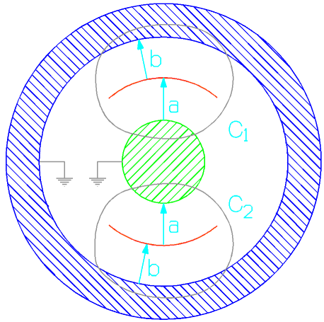
Figure 2.11 Schematic drawing of the two capacitance sensor of the bridge of the GG read out system for detecting relative displacements of the inner and outer test body with respect to one another. Each capacitor is formed by two surfaces, one for each of the two grounded bodies, and one plate, to which a sinusoidal voltage is applied. The other two capacitors of the bridge are fixed capacitors. Any differential displacement of the test masses with respect to the plates causes a loss of balance of the bridge and therefore an output signal.
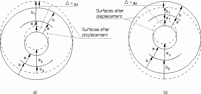
Figure. 2.12 The surfaces of the capacitors before and after: a) a common mode displacement and b) a differential mode displacement. For a non zero
(a-b) both a differential and a common mode displacement would contribute to the (capacitance) unbalance of the bridge, hence to the output potential, as in Eq. (2.14). An EP violation signal would produce a differential displacement. For it to be detected the contribution coming from a common mode displacement (e.g. caused by air drag) must be smaller than the contribution of the EP violation, hence leading to the constraint on the mechanical unbalance of the bridge (a-b)/a (see inequality 2.15).
2.1.4 Balancing of the Test Bodies and Common Mode Rejection
The effect of non gravitational forces, such as air drag and solar radiation pressure, acting directly on the outer surface of the spacecraft and not on the suspended masses inside, is twofold. On one side they shake the spacecraft and produce vibration noise whose spectral distribution covers a wide frequency range and depends on the particular spacecraft. This is not a matter of concern for the GG experiment thanks to the PGB mechanical suspension which is particularly effective at the
2 Hz modulation frequency the signal (Fig. 2.6). On the other side, non gravitational forces accelerate the satellite itself. Let us consider air drag, which at 520 km altitude dominates over solar radiation pressure (the effect of the Earth's albedo is even smaller). The main component of air drag is in the along track direction of the satellite with smaller variations at higher frequencies. The spacecraft will loose altitude and accelerate in the along track direction, with the result that the suspended bodies inside (the PGB laboratory as well as the test masses) will be subject to inertial translation forces. These are transferred to the PGB via its helical suspension springs and, from the PGB, via the flat elastic gimbals connecting the PGB to the coupling arms of the test bodies (see Fig. 2.1), to the test bodies themselves. We have shown already that the spin axes are essentially unaffected by the various disturbances because of the high spin energy of the bodies. The lifetime of the satellite because of its orbit decay is several tens of years, much longer than the 7 months total mission duration.The first important fact to learn is that, unlike the forces which act directly on the surface of the spacecraft, inertial forces on the suspended bodies inside do not depend in any way on the surface properties of these bodies. Whatever the non gravitational acceleration on the satellite, the inertial acceleration transferred to the coupled test bodies is simply opposite to that acquired by the spacecraft because of drag; and if the test bodies are perfectly balanced, there is no differential displacement between the two. In such an ideal case, drag would not affect the expected signal of an EP violation at all since this is differential. The mathematical dynamical model equivalent to the GG coupled test bodies is shown in Fig. 2.13, from which it is apparent that the system is in all similar to an ordinary beam balance, save for the fact that it is a vertical rather than a horizontal balance. Although not perfectly balanced so as to be totally unaffected by drag, the system can be balanced in order to reject common mode forces (such as the inertial forces resulting from drag) to very high accuracy, leaving only a much smaller differential residual disturbance to compete with the signal. Piezoelectric actuators are well suited to accurately balance the system, as shown in Fig. 2.14. The required electric connections are through the flat gimbals (as discussed in Sec. 2.1.1) and, by using inch-worms, all tensions can be switched off after balancing.
Once no further reduction is possible the phase and frequency of the signal must be analyzed in order to establish whether it is due to an EP violation. How can one make sure that an EP violation signal would not be eliminated together with the perturbing effects? This would only be possible for a competing effect with the same frequency and phase as the signal, and in the case that it were also constant in time. If the effects of drag and EP violation were parallel to each other one could, for one particular value of the drag, balance the sum of the two. However the drag is approximately along track, i.e. approximately at
90° with the EP violation signal. Since we know the exact direction of the latter (toward the Earth's center), we can perform a balancing, exactly at 90° with respect to it, of the main component of the drag. Once its main component has been balanced, also a possible component of the drag parallel to the EP violation signal will be balanced out, as well as all variations of the drag and all other common mode effects. In this way the EP violation signal will not be affected, and will be the only remaining.It is apparent that the weaker the force, the more accurate can be the balance, hence balancing the GG test bodies in space is favored by the very weak effect of drag (much stronger than the expected signal, but much weaker than
1-g on Earth!). The test bodies of the GGG prototype have been balanced to 1 part in 200,000 (see Chap. 3), better than it is currently required for GG in space (see Sec. 2.2.1 for the requirements)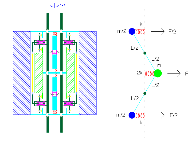
Figure 2.13 The GG system of coupled test bodies (shown in Fig. 2.1 and discussed in Sec. 2.1.1) is equivalent to the mathematical model shown on the right, which is in essence a vertical balance. F represents any force acting on the system in common mode (i.e. the same on both bodies); being the beam of the balance vertical, it can balance forces in the horizontal plane (i.e. the orbital plane). F represents here the main effect of drag as the GG satellite orbits around the Earth (orbit frequency). It is apparent that if the arm lengths and masses were exactly equal F would cause no relative displacement of the centers of mass of the bodies one with respect to the other. An EP violation signal would be also in the horizontal plane, but at about 90° from F , i.e. about normal to the plane of the figure.
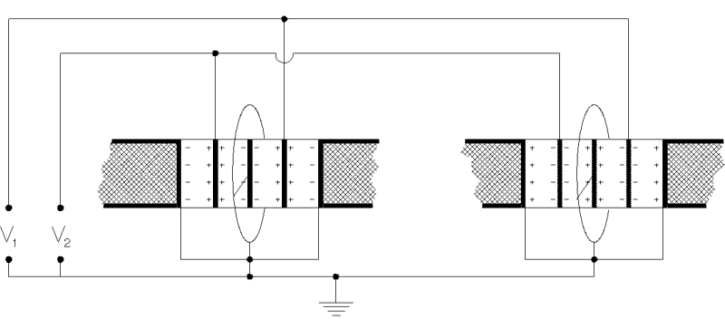
Figure 2.14 An enlarged view of the system of piezoelectric actuators placed on the two balancing arms of the GG test bodies (see Fig. 2.1 for an overall view). The + and - signs represent the intrinsic polarization of the actuators, i.e. how each one of them must be oriented when mounted. Control voltages are applied to the actuators (when they are applied with the opposite polarity they should not exceed a certain value, which however is relatively high, so as not to risk to depolarize the piezoelectrics): the sum V1+ V2 determines the relative axial position of the centers of mass of the test bodies and is used for axial centering. The voltage difference V1- V2 can be used to change the lengths of the four halves of the arms so as to balance out the effect of transverse inertial forces (in particular the along-track component of the air drag).
2.1.5 Self-centering, Whirl Motions and Stabilization
The GG experiment requires the test bodies, as well as the PGB
laboratory, to be weakly coupled and rapidly spinning, which means that the frequency of
spin is much higher than all frequencies of natural oscillation: w
s>>w n. This is known as supercritical rotation. Rotors in
supercritical rotation are known since the last century to have an equilibrium position
very close to the rotation axis, which is pivotal in reducing the otherwise destructive
effects of centrifugal forces. In simple terms, a weakly suspended fast spinning rotor
tends to spin around its center of mass, i.e. it behaves more like a free rotor rather
than a constrained one. If the center of mass of the suspended body is located, by
construction and mounting, an offset vector ![]() away from the rotation axis, equilibrium is reached on the opposite side of
away from the rotation axis, equilibrium is reached on the opposite side of ![]() with respect to the rotation axis, where the
centrifugal force due to rotation and the restoring elastic force of the suspension equal
each other. It can be shown that this happens at a distance from the spin axis smaller
than the original unbalance
with respect to the rotation axis, where the
centrifugal force due to rotation and the restoring elastic force of the suspension equal
each other. It can be shown that this happens at a distance from the spin axis smaller
than the original unbalance ![]() by a factor
by a factor ![]() (see e.g. Den Hartog, Chap. 6, 1985; Genta,
1993). Thus, at equilibrium, the off-centering is:
(see e.g. Den Hartog, Chap. 6, 1985; Genta,
1993). Thus, at equilibrium, the off-centering is:
 (2.16)
The offset vector ![]() ,
hence also the equilibrium position vector, are fixed with the rotor. Since the pioneer
work of Gustaf De Laval about a century ago this relationship has been widely demonstrated
in both theoretical and experimental work on high speed rotors. It shows that space offers
an important advantage, because in absence of weight the natural frequencies of suspended
bodies can be made very low. In GG the ratio w s/w n goes from 250 to 1000, hence
the reduction factor of the initial offset given in Eq. (2.16) goes from 10-6 to 1.6× 10⁻⁵. Moreover, it is purely passive, naturally deriving from physical laws. For an
original unbalance e @ 10 m m this means that the equilibrium position is within @ 1 Angstrom from the spin axis, as we
have indeed verified in the numerical simulation of the GG system (see Chap. 6, Fig.
6.29). It is important to stress that this equilibrium position, slightly displaced from
the rotation axis, is fixed in the rotating frame of the spacecraft while the signal is
modulated at the frequency of spin. Possible imperfections on the surfaces of the bodies
would also give a DC effect. The actual direction of the off-centering in the rotating
system depends only upon the location of the unbalance and is of no importance for the
experiment.
,
hence also the equilibrium position vector, are fixed with the rotor. Since the pioneer
work of Gustaf De Laval about a century ago this relationship has been widely demonstrated
in both theoretical and experimental work on high speed rotors. It shows that space offers
an important advantage, because in absence of weight the natural frequencies of suspended
bodies can be made very low. In GG the ratio w s/w n goes from 250 to 1000, hence
the reduction factor of the initial offset given in Eq. (2.16) goes from 10-6 to 1.6× 10⁻⁵. Moreover, it is purely passive, naturally deriving from physical laws. For an
original unbalance e @ 10 m m this means that the equilibrium position is within @ 1 Angstrom from the spin axis, as we
have indeed verified in the numerical simulation of the GG system (see Chap. 6, Fig.
6.29). It is important to stress that this equilibrium position, slightly displaced from
the rotation axis, is fixed in the rotating frame of the spacecraft while the signal is
modulated at the frequency of spin. Possible imperfections on the surfaces of the bodies
would also give a DC effect. The actual direction of the off-centering in the rotating
system depends only upon the location of the unbalance and is of no importance for the
experiment.
Offset values e significantly smaller than 1m m (even by a factor 100) are achieved with ground rotors; however, it has been pointed out by Cornelisse (1996) that the system of test bodies cannot be tested on the ground in exactly its flight configuration; therefore we assume that the initial offset of the GG bodies, by both construction and mounting imperfections, does not exceed the value e =10 m m. It should be realized that, from the viewpoint of modern capabilities in precision mechanics this is a very conservative assumption.
Perturbations such as air drag and solar radiation pressure acting on the external surface of the spacecraft produce a non gravitational acceleration of its center of mass. In the reference frame of the spacecraft the bodies will therefore be subject to inertial forces in the opposite direction, which will move the masses to new displaced positions of equilibrium where the perturbation is balanced by the restoring force of the spring. This is shown very clearly in Fig. 6.4 obtained from the numerical simulation (Fig. 6.4 shows also the whirl, that we introduce below). It is worth noticing that, because of the supercritical state of rotation, the displaced body will always spin around its own axis, which means that no centrifugal force due to the spin will result because of this displacement. The only centrifugal force due to the spin come from the off-centering given by Eq. (2.16) and is balanced by the restoring force of the suspension springs.
No matter how good is the mechanical quality of the suspensions and how accurately they are clamped, as the system rotates they will undergo deformations and, in this process, will dissipate energy. The only energy that can be dissipated is the spin energy of the rotor, which means that the spin angular velocity must decrease. As a consequence, the spin angular momentum also decreases, and since the total one must be conserved, a motion of the two bodies one around the other (in the same direction as the rotational motion) will develop. Which is what is observed, and is referred to in the literature on Rotordynamics as whirling motion. Friction between rotating parts of the system (i.e. friction inside the suspension springs) is the physical cause of the whirl motion, and it is referred to as rotating damping. Except in the case of rotating machines with very viscous bearings, the rotor whirls at essentially its natural frequency (with respect to a fixed frame of reference). In GG there is no motor, there are no bearings, no fluids, no oils, no greases; only carefully clamped suspensions of high mechanical quality (particularly for the test bodies) which undergo only minute deformations. Hence, the GG bodies whirl at their natural frequencies of oscillation.
As shown in Sec. 2.1.4, it is a key feature of GG that the test cylinders be very weakly coupled in the plane perpendicular to the spin axis, so as to be sensitive to tiny differential forces in the transverse plane (close to the orbit plane). The mathematical model typically used in Rotordynamics literature in order to describe this system is shown in Fig. 2.15, where rw is the radius of whirl of each body around the common center of mass which, for the purpose of the present discussion on whirl motion, is shown to coincide with the equilibrium position ("perfect'' self alignment); this amounts to neglecting the off-centering at equilibrium given by Eq. (2.16), which is of about 1 ® for the test bodies (as it has been confirmed by numerical simulations; see Fig. 6.29).
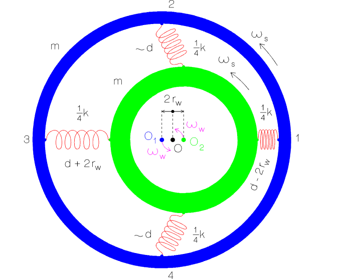
Figure 2.15 Mathematical model of a rotor made of two bodies, each of mass m, coupled by weak springs. The coupling constant is k and the natural frequency of oscillation
wn. Both bodies are spinning at the same angular velocity ws around their respective centers of mass O1 and O2. In turn, O1 and O2 are whirling around the center of mass O of the whole system, at a distance rw (the whirl radius) from it, and at the natural angular velocity wn. In the GG case wn @ 10-3 ws.Can the whirl motion be damped and the rotating system be stabilized? For more details than those given in the remaining of this Section see: Bramanti et al., 1996; Nobili et al., 1996; Nobili et al., 1997b; Nobili et al., 1997c.
If there is nothing else in the system but rotating damping there is nothing to prevent the amplitude of the whirl motion from growing, and therefore the system is unstable. In rotating machines on the ground whirl motions are usually damped by non-rotating damping, namely by sufficient friction occurring between two parts of the system, both non-rotating as shown in Fig. 2.16 (i.e. between two parts of the non-rotating supports, for example friction between the non-rotating part of the bearings and their fixed supports). This friction generates non-rotating damping forces which are effective in damping transversal translational oscillations of the rotor's axis of rotation (such as the whirl motions), and they do so without slowing down its rotation.
Non-rotating friction should not be confused with friction in the bearings, also shown in Fig. 2.16. This is the friction (mostly viscous) between the rotating body and the non rotating parts, which is obviously effective in slowing down the rotor but almost completely ineffective at damping whirling motions (and also at producing them). An important advantage of the GG space experiment is the absence of bearings, hence of bearing friction at all.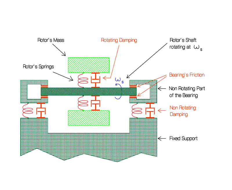
Figure 2.16 Sketch of a ground rotating machine showing where
rotating damping, non-rotating damping and friction in the bearings are localized. The different rôles they play in the dynamics of the system are discussed below.In the GG space experiment where there are no non-rotating parts an equivalent non-rotating damping must be provided by an active control system of sensors and actuators fixed with the rotating bodies. Before any such device can be designed, it is obviously necessary to establish the magnitude of the forces which destabilize the system and which will therefore need to be counteracted actively. The actual implementation of the active control forces for the real case, with realistic errors in all components of the control system, can only be faced once the magnitude of the destabilizing forces has been firmly established. In turn, this requires to firmly establish the amount of energy losses in the GG rotating system.
GG is made of rigid bodies coupled by weak suspensions of high mechanical quality (particularly those of the test bodies) which moreover undergo only minute deformations, from a few
10-3 m m in the case of the test bodies to @ 0.6 mm in the case of the PGB (before drag compensation); see Sec. 2.2.1. The suspensions are carefully clamped so as to avoid parts sliding one against the other, which is the main cause of mechanical losses. There are no bearings, since, after spin up is completed, there is no need of a motor. There are no viscous materials: no fluids, no oils, no greases. Therefore the main loss factors (inverse of quality factor Q) are those due to the very small internal dissipation of the mechanical suspensions as they undergo minute deformations at the spin frequency. The only other cause of dissipation are the electrostatic sensors/actuators used to damp the whirl motions, since all other parts are rigid and have no losses. Calculation of thermal noise in the active dampers shows that the corresponding losses are by far negligible compared to those achievable with mechanical suspensions (assuming all parameters as for the GG experiment and a very conservative value of 10 for the electric quality factor); see Nobili et al., 1997a; 1998a. Crandall (1997) has calculated the back-reaction force on the plates of the capacitors from the high-frequency measurement voltage, finding that the electrical contributions to the mechanical stiffness and damping are negligible.A firm estimate of the losses in the GG mechanical suspensions requires them to be measured experimentally, by setting the springs in oscillation under realistic operating conditions (oscillation frequency, vacuum, temperature, clamping); note that there is no need to perform this measurement with the system rotating (Crandall and Nobili, 1997; from S.H. Crandall on the subject of damping in Rotordynamics see also Crandall, 1970; Nelson and Crandall, 1992; Crandall, 1995).
In order to measure, for a given mechanical system, the quality factor
Q (defined as the ratio of the total energy stored in the system to the amount of energy dissipated in one cycle) the system is made to oscillate and then the oscillation amplitude A(t) is recorded as it decays with time. Q can also be expressed as follows:![]() (2.17)
(2.17)
where w is the frequency of the oscillation and
A(0) its amplitude at initial time. Hence:![]() (2.18)
(2.18)
which yields the value of
Q from measurements of A1, A2 at times t1 t2. Consider a helical spring with its (unavoidable) clamping and the attached mass necessary to obtain the oscillation frequency of interest. Horizontal oscillations avoid pendulum-like motion due to local gravity which would yield a higher Q because gravity contributes to the total energy but not to the dissipation. In vacuum (@ 10-5 torr) at room temperature and for oscillation frequencies from 2 to 10 Hz, the measured Q values of the prototype springs manufactured for the suspension of the GG test masses were between 16,000 and 19,000. Oscillations were excited with a small electromagnet and their amplitudes were measured optically. Fig. 2.17 shows the Q measurement apparatus used and the way the helical spring of the GG test bodies (see Fig. 2.2) was mounted. Although further improvement is possible, these values are quite good because of the complex shape of the suspensions. The Q measurement procedure (by recording the decaying oscillation amplitude) is a standard one, which obviously does not require the system to be taken into space even though, in this case, it is designed for use in space.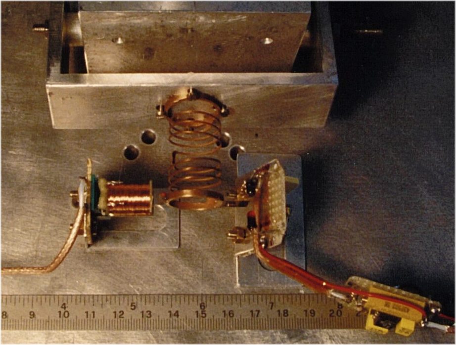
Figure 2.17 One helical spring to be used for suspending the GG test bodies (see Figs. 2.1 and 2.2) clamped and ready for measuring its quality factor at a frequency of a few Hz. A small mass is attached to the free end of the spring in order to obtain the desired oscillation frequency. Note that the measurement is done for horizontal oscillations for the result not to be affected by local gravity
Similarly, the quality factor of one helical spring to be used for suspending the PGB laboratory has been measure, yielding a value of
90. This low value is due to the fact that this spring has 3 Cu wires for electrical connections insulated and glued with epoxy, as described in Sec. 2.1.1 (Fig. 2.5). As discussed there and shown in Fig. 2.6, this is not a problem from the point of view of vibration isolation (although a higher Q can be easily obtained using separate wires insulated at the clamping). It is also not a problem from the point of view of whirl motion, as shown below and verified in detail with numerical simulations (Chap. 6).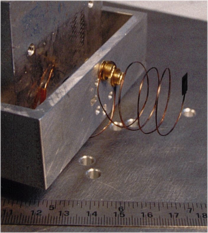
Figure 2.18 One helical spring manufactured for suspending the PGB laboratory clamped and in preparation for the measurement of its quality factor in horizontal oscillations at frequencies of a few Hz (the small black sheet at the free end of the spring is for the optical measuring system).
Energy is dissipated because of different types of losses (structural or viscous, in the spring material as it undergoes deformations, because of imperfect clamping or because of the resistance of residual air) and the oscillation amplitude decay is due to all of them. Consequently, the measured
Q is the Q of the whole system and gives a quantitative measurement of all losses in it: whatever their physical nature.Since energy losses in the mechanical suspensions are responsible for the onset of the whirl motion (in order to conserve the total angular momentum of the system) (see Fig. 2.15), the whirl motion (at the natural frequency w
n w.r.t. the fixed frame) is nothing but an oscillatory motion of growing amplitude, i.e. with a negative quality factor equal and opposite to the measured quality factor Q of the suspensions. Hence, the radius of whirl will grow, from a given initial value rw(0), according to the equation:![]() (2.19)
(2.19)
That is, the larger the
Q, the slower the growth of the whirl instability. For large Q, as in this case, we can write:![]() (2.20)
(2.20)
where (D
rw)Tn is the increase in the amplitude of whirl in one natural period of oscillation Tn. For the GG test bodies, taking the measured value Q @ 19,000 and having Tn @ 113 sec (see Sec. 6.1.10), the amplitude of the whirl motion will need 8 days to double: such a very slow growth of the whirl instability is obviously very important for making the control forces required to damp it very small. For the PGB, with a Q value of 90 and a natural period of oscillation of about 300 sec the amplitude of the whirl motion needs about 2.4 hours to double; clearly, the whirl motion of the PGB grows much faster than the whirl motion of the test bodies due to the much poorer mechanical quality of its suspensions. However, it is still very slow compared to the spin and there is no problem in controlling it, as it is found in Chap. 6. The disturbing force resulting from inaccurate application of the PGB control force acts as a common mode disturbance on the test bodies (platform noise) and it is found to be negligible (see Sec. 2.2.6).The increase in amplitude (D
rw)Tn (during one natural period) is due to an increase of the along-track velocity of the bodies, which in turn is caused by an average destabilizing acceleration ad, also along-track, such that:![]() ,
, ![]() (2.21)
(2.21)
which means, an average destabilizing force (along-track) of magnitude
![]() (2.22)
(2.22)
Since ![]() is the
centrifugal force, equal and opposite to the elastic force of the spring
is the
centrifugal force, equal and opposite to the elastic force of the spring ![]() , the destabilizing force which generates the
unstable whirl motion depicted in Fig. 2.15 turns out to be
, the destabilizing force which generates the
unstable whirl motion depicted in Fig. 2.15 turns out to be
![]() (2.23)
(2.23)
i.e., only a fraction of the elastic spring force: the higher is the
Q of the suspensions (at the spin frequency) the smaller is the destabilizing force which needs to be damped in order to stabilize the system. This is well known in Rotordynamics.The following question becomes relevant at this point: how much energy (per unit time) is gained by the (destabilizing) whirling motion as fraction of the energy lost by the spinning rotor? Let us consider the rotor in the two body model of Fig. 2.15. The spin energy of the rotor is:
![]() (2.24)
(2.24)
I is the total moment of inertia of the two bodies with respect to the spin axis (perpendicular to the plane of the Figure). The energy (kinetic plus elastic) of the whirl motion, at the constant natural frequency w
n with respect to the fixed frame and with radius of whirl rw is:![]() (2.25)
(2.25)
The time derivatives of
Ew and Erotor are:![]() ,
, ![]() (2.26)
(2.26)
From the conservation of angular momentum it is possible to relate ![]() to
to ![]() . The total spin angular momentum of the rotor is:
. The total spin angular momentum of the rotor is:
![]() (2.27)
(2.27)
The angular momentum of the whirl motion is:
![]() (2.28)
(2.28)
Since the total angular momentum has to be conserved, it must be:
![]() (2.29)
(2.29)
from which, since w
n is constant, it follows:![]() (2.30)
(2.30)
Using Eq. (2.30) for![]() , we
get from Eq. (2.26):
, we
get from Eq. (2.26):
![]() (2.31)
(2.31)
which is a very important result. In the GG case, where the frequency of the whirl motion is very small compared to the spin frequency
(w n @ 10-3 w s), Eq. (2.31) tells us that the energy gained by the whirling motion is one thousand times smaller than the energy lost by the rotor. All the rest, that is 1-(w n/w s) @ 99.9%!! is dissipated as heat inside the springs; which means that it is not transferred to the (destabilizing) whirl motion. In simple terms one can say that in "supercritical'' rotation the energy balance is essentially between the rotor and the springs; the rotor looses spin energy and the springs dissipate almost all of it as heat: the faster is the spin, the larger is the energy dissipated inside the springs, as it can be seen from Eq. (2.26). On the other hand, the springs do not enter at all in the balance of the angular momentum; the onset of the whirl motion is inevitable for the total angular momentum to be conserved, but the energy it gains from the rotor is only the small fraction given by Eq. (2.31). So, the idea one might have that the faster the spin (as compared to the natural frequency) the higher the energy gained also by the whirl motion (by which argument the GG system would be highly unstable), is proved to be incorrect. As a consequence, the GG system is not more unstable than ground based rotating machines because of the smaller ratio w n/w s (by one order of magnitude or more), because the fraction of destabilizing energy is also correspondingly smaller, as shown by Eq. (2.31).Active Stabilization and Control with Rotating Dampers. All the GG bodies spin at the same rate. Phase lags between the PGB and the outer spacecraft induced by eclipses are compensated (see Sec. 2.1.2); initial phase lags between the test cylinders and the PGB due to unlocking are damped out by the coupling springs (see Sec. 2.1.6). There are no non-rotating parts, and therefore there can be no non-rotating friction to damp the whirl motions. They must be damped actively, with dampers necessarily fixed to the rotating bodies. We have shown (Eq. 2.26) that the destabilizing forces are only a small fraction of the passive spring forces, which in turn are very small because the suspensions are designed to be extremely weak
(k @ 10-2 N/m=10 dyn/cm), as it is in fact possible in space in spite of the fact that the test bodies have masses of 10 kg each. Small capacitance sensors/actuators (see Fig. 2.19; also shown in the overall view of Fig. 2.8), with surfaces of about 2 cm2, turn out to be sufficient to provide the required active forces.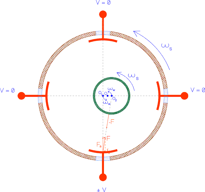
Figure 2.19 Four capacitance plates, at 90° from one another, rotate with the system at angular frequency
ws. They provide an electrostatic force F in order to prevent the growth of the whirl motion of the bodies (at a frequency ww equal to the natural one wn). The reaction of the active force on the plate has a small tangential component fa which spins up the rotor by transferring to it the angular momentum of whirl, which would otherwise grow. The figure is not to scale; the distance 2.rw between the centers of mass O1 and O2 of the two bodies is in reality many orders of magnitude smaller than the radius of this device.Let the whirling motion be damped using electrostatic sensors/actuators fixed to the rotating bodies. The capacitors are required to provide a force at the whirling frequency w
n while spinning at angular frequency w s; therefore, they must actuate at frequency w s-w n. By providing forces internal to the system they cannot possibly change its total angular momentum: they can only transfer the angular momentum of whirl to the rotation angular momentum of the rotor by spinning it up. This is what happens if they are made to provide a stabilizing force of the same intensity as the destabilizing one given by Eq. (2.23) (in fact a slightly larger one). This force must always act along the vector of relative velocity of the centers of mass of the bodies in their whirling motion, as seen in the fixed frame of reference. Since the centers of mass of the bodies are displaced from the center of mass of the system by an amount rw (see Fig. 2.19), the electrostatic plates will necessarily apply also a small force fa tangent to he surface of the rotor amounting to a fraction rw/R (R @ 10 cm is the linear dimension of the rotor) of the active force F, of intensity F @ (2/Q).|Fspring| (for both bodies), which will damp the relative velocity of whirl (see Fig. 2.19). Of the corresponding reaction components on the electrostatic actuators only the reaction to the small tangential component fa @ (1/Q).|Fspring|.(2rw/R) will produce a non zero angular momentum by spinning up the rotor at the expense of exactly the angular momentum of whirl:![]() (2.32)
(2.32)
which will therefore increase the spin angular momentum of the rotor
Lrotor = I.w s in such a way that the total angular momentum of the system is conserved. That is:![]() (2.32)
(2.32)
thus producing a spin up of the rotor at the rate ![]() given by Eq. (2.32) By integrating
given by Eq. (2.32) By integrating ![]() for the entire duration of the mission
for the entire duration of the mission
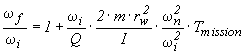 (2.33)
In the case of the GG test bodies, taking the measured value of
19,000 for the quality factor Q at the spin frequency of 2Hz, rw @ 10-2 m m (although whirl radii are damped below this value) and![]() (2.34)
(2.34)
The corresponding angular advance is negligible. The amount of spin energy gained by the rotor at the end of the mission is vanishingly small. The corresponding (negative) quality factor for the spin up of the rotor (in absence of any external disturbances to its spin rate) is obviously huge (in modulus). The amount of spin angular momentum gained by the rotor in
6 months is, similarly to the spin energy, vanishingly small.The contribution to the energy of the system by the electrostatic dampers is obtained by computing the work done by both components (
Fa and fa, shown in Fig. 2.17) of the active force they provide. While only fa will transfer angular momentum from the whirl motion to the rotor, both components of the active force will provide energy. It can be easily demonstrated that fa supplies the rotor with the energy necessary to increase its spin rate, while the energy supplied by Fa balances exactly the energy dissipated by the springs as heat, which would otherwise slow down the rotor.The capacitors must also act as sensors in order to recover, from relative position measurements, the linear relative velocity of the whirling motion which needs to be damped to stabilize the system; or, for example (see Fig. 2.19), two of the capacitors can be used as sensors and the other two as actuators. In GG the capacitors spin (together with the bodies) at a frequency about 103 times larger than the frequency of whirl. Is it possible, by means of rotating sensors, to recover the slow relative velocity of whirl as with non-rotating sensors? This question can be answered in a totally general way. The answer would be "No", if the rotating observer had no other means of "looking outside" to measure independently (i.e. by means of some other instrument) its own phase and rotation rate; the answer is "Yes", if the rotating observer can do that, which is the case in GG using Earth Elevation Sensors (see Sec. 5.5). An independent knowledge of the phase and the rotation rate of the sensors makes it possible to subtract from the measurements of the rotating sensors their own velocity of rotation, hence to recover the (much slower) relative velocity which would be obtained with fixed sensors. The problem amounts to that of computing numerically a time derivative, because the capacitors measure relative displacements while the electrostatic active dampers require to know the relative velocity of the bodies in the fixed frame. If the velocity were computed by taking successive measurements of the sensors and computing their difference, it would be dominated by the rotation velocity, i.e. it would be larger than the velocity to be damped by a factor about
103 (i.e. the ratio spin-to-natural velocity). If then such a velocity output were used to drive the electrostatic actuators which must damp it, the required force would be (correspondingly) about 103 times larger than necessary. Clearly this procedure would not be appropriate for a system like GG where the spin-to-natural velocity ratio is very large.Instead, the problem of reducing the magnitude of the active control forces close to that of the destabilizing ones (given by Eq. 2.23), is solved as follows. A reference signal is built from a 2 Hz oscillator (clock) synchronized by the Earth Elevation Sensors output averaged over many spin periods of the spacecraft. Since the spin period is
0.5 sec, it can certainly be considered constant over time intervals of the order of many times the spin period itself. Note that the reference signal is continuously synchronized to the output of the Earth Elevation Sensors so that any error in their measurement of the spin rate will not build up. The reference signal is needed in order to perform the transformation from the rotating to the fixed frame (and back) as accurately as possible. A relative displacement of two bodies due to the growing unstable mode is measured by the rotating capacitance sensors. Instead of taking successive measurements of the sensors and computing their difference, the difference is computed between measurements which are 1 spin period apart, using the reference signal. The sensor signal is sampled a certain number of times per spin period (e.g. 10 to 20), at regular intervals, and for each sampled point the difference is computed with respect to the sampled point 1 spin period later. In this way the rotation velocity of the sensors is subtracted from their measurements; a best fit to the sampled data points (each one is a relative position difference after 1 spin period) gives the relative velocity vector![]() (2.35)
(2.35)
This force will prevent the whirl motion from growing, i.e. it will
maintain the system in a steady condition. To actually damp a whirling motion one has to
apply a slightly larger force: for instance, a force twice as large will damp the whirling
motion at the same rate at which it would grow in the absence of ![]() .
.
Were the capacitance sensors perfect, this would be enough to stabilize the GG bodies, as it can be also checked with numerical simulations. However, the sensitivity of the sensors in realistic flight conditions has to be taken into account because, being the growth rate of the whirl instabilities very slow, the relative displacement during one spin period is so small to be dominated by the noise of the sensors. As a result, the recovered velocity vector is also very noisy, and much larger than its actual value in the fixed frame. If the actuators were programmed to damp the velocity vector recovered in this way, the resulting active force would be driven by the noise, i.e. it would be much larger than the force which destabilizes the system. Such a controlled system would be dominated by the active control forces rather than by the very low stiffness passive mechanical suspensions. This is in contrast with the basic physical design of the GG experimental test of the universality of free fall whereby the test bodies must be very weakly coupled so as to be sensitive to tiny differential forces.
A better active control can be devised in which active damping is not applied until the (slow) relative velocity of the whirl motion of the bodies has been recovered from the noise after appropriate averaging. To do this, the relative velocity vector is averaged over a few spin periods (typically a fraction
1/100 of one period of whirl), and then fitted to the whirl period (the natural period of oscillation) in order to reconstruct its rotation in the fixed frame. Since the growth rate of the instability is slow, this averaging procedure can be carried on over a large number of whirl periods (particularly for the test bodies), thus making the determination of the velocity to be damped more and more accurate. Active control starts only once the small relative velocity of the bodies w.r.t. the fixed frame has been reconstructed and separated from the noise.So far we have outlined the main principles on which active control of the whirl motions should be based. A dynamical control which allows stabilization of the whirl motions (as well as drag compensation according to the requirements) has been designed and implemented in a finite element numerical simulation of the full GG system. The results are reported in Chap. 6 and are fully satisfactory. They demonstrate beyond question that the analysis of GG by Jafry and Weinberger (1998), whereby GG would be limited by the active control forces to an accuracy of
1 part in 1014 in EP testing (3 orders of magnitude worse than the GG target), is incorrect because their dynamical control is badly designed (see also Nobili et al.,1998b).
2.1.6 Locking/Unlocking
All space experiments which involve freely falling or softly suspended bodies require them to be locked during launch, and properly unlocked once in orbit to start the experiment. First of all we find it important to avoid any danger of the rotors hitting each other. This is done simply by having each suspended mass and the PGB laboratory constrained to only slight movements in all directions by means of mechanical stops Fig. 4.3 shows, for instance, the mechanical stops between the outer test cylinder and the PGB tube. Static lockers capable to survive the launch phase have been designed both for the PGB (Sec. 5.2) and the test bodies (Sec. 4.1). As for the forces acting on the springs themselves during launch, their mass is very small and estimates show that there is no danger for the elasticity regime to be exceeded during launch; some time for relaxation should probably be allowed at the beginning of the mission. Once the spacecraft has been injected in its orbit and given the required attitude and spin rate static lockers can be released and never used again. A symmetrical locking consisting of
4 inch-worms placed at 90° from one another as shown in Fig. 2.20 is provided, centering the cylindrical bodies to within their original construction and mounting error e @ 10 m m (see Sec. 2.1.5). Each inch-worm is equipped with a force sensor sensitive to 10 m N (easy, e.g. with a spring force sensor) giving a measure of the centrifugal force in that direction, and therefore providing the driving signal to the inch-worms for reducing the distance offset from the rotation axis. Once the off centering has been reduced to @ 10-9 m, which means a centrifugal force of 10 m N for the PGB, active centering with inch-worms can be stopped; the electrostatic dampers will then stabilize whirl motions around the equilibrium positions (see Sec. 2.1.5 and Chap. 6). While the static lockers are meant not to be reused, the inch-worms can be reused to re-center the system if anything happens during the mission. Together with the mechanical stops they make the system safe from unexpected occurrences.The inch-worm unlocking should be done without transferring spin angular momentum to the bodies, which would induce undesired differential rotations. Ideally, the rotational torque provided by inch-worms placed at
90° from one another and pointing exactly towards the central axis, is exactly zero. This is why this configuration of the inch-worms has been chosen. The time required to provide the required force is very short (order of seconds). In practice however, there will be both angular and linear offsets from the ideal inch-worm configuration resulting in a non zero rotational, spurious torque whose effect on the springs which couple the bodies must be carefully evaluated. Most of the spurious torque is induced at the beginning of the inch-worm unlocking, when the off-centering of the body is dictated by the offset e of the test bodies due to construction and mounting imperfections. Assuming, for the angular and linear offsets of the inch-worms 0.1 rad (6° ) and 1 mm (both very conservative with modern precision mechanics), and a continuos control time of 50 sec, the resulting spurious phase lag is 0.01 rad. Such a small phase lag, obtained under conservative assumptions, is reduced to zero by the torsion constant of the coupling springs over timescales of the order of 2 days for the PGB and 2 weeks for the test masses (Comandi,1998).The rôle of the coupling springs in damping out small phase lags between the PGB and the GG test bodies inside it, is very important and should not be overlooked. This is unlike the phase lags between the outer spacecraft and the PGB laboratory which are induced by eclipses every orbit; as discussed in Sec. 2.1.2, these phase lags are reduced almost entirely by a passive mass compensation system, and the small remainder by FEEP control.
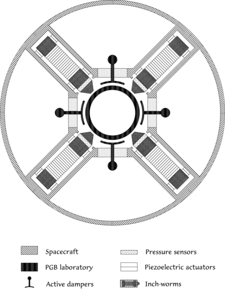
Figure 2.20 Top view (across the spin/symmetry axis) of one set of 4 inch-worm actuators for fine unlocking of the suspended GG bodies; this figure refers to unlocking the PGB from the outer spacecraft. The inner tube less than 10 cm in radius (belonging to the PGB) encloses one of the PGB helical suspension spring. As viewed in Fig. 2.8, this system is located at the top (or bottom) of the PGB suspensions. Since Fig. 2.8 is a section through the spin/symmetry axis, the capacitance active dampers and the inch-worms cannot be shown together (each damper is 45° from the two nearest inch-worms); Fig. 2.8 shows only the capacitance dampers. Each suspended cylinder needs 2 sets like the one shown here placed at its two axial ends.
2.1.7 Calibration Procedure
Once the GG rotors have been properly unlocked, as outlined in the previous Section the small capacitance sensors/actuators shown in Figs. 2.1 and 2.8 can be put in operation. It is the task of the fine unlocking inch-worm system described in Sec. 2.1.6 to bring all relative distances of the GG bodies (the PGB with respect to the spacecraft and the test bodies with respect to the PGB) within the control capability of the small capacitors (i.e.
À 10-2 m m; see Chap. 6). The dynamical control of whirl motions (as simulated in Chap. 6) can therefore begin. After whirl control is in operation and working properly, drag-free control can also begin, driven by the PGB small capacitors which sense the relative displacements of the PGB with respect to the spacecraft; according to the numerical simulations reported in Chap. 6, full dynamical control (for both drag compensation and whirl damping) works properly. Note that, for the control to work properly the value of the spin angular velocity must be known to 1 part in 104 (rms) (see Chap. 6 and Sec. 5.5); however, the angular velocity is not required to have a specific value, as long as it is close to the nominal value for which the satellite has been designed.At this point data taking can begin from the main read-out capacitance sensors shown in Fig. 2.1 through a synchronous demodulation of the
2-phase 2 Hz signal, since we know that the signal of interest is modulated at 2 Hz. This is in all similar to what we do already with the GGG prototype in the laboratory (see Chap. 3). The circuits currently mounted and used in GGG for the 2-phase synchronous demodulation of the signal at the spinning frequency are shown in Fig. 3.11.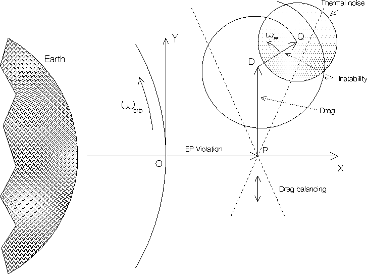
Figure 2.21 Qualitative representation, in the orbital plane, of the differential displacements obtained from the synchronous demodulation of the 2-phase 2 Hz signal. The X axis is fixed in the Earth-to-satellite direction; in this non spinning frame the OP vector represents the expected signal, namely a differential displacement, directed along the X axis and constant in amplitude, of the two masses due to a violation of the Equivalence Principle violation. The perturbation PD due to an unbalanced atmospheric drag will be found in the area between the two dotted lines crossing in P: The angle between them is about 0.8 rad, due to the fact that the drag has a variable component in the radial direction because of solar radiation pressure (of amplitude about 0.4 times the atmospheric drag and in the Sun-satellite direction). Smaller contributions to the PD vector come from the Earth albedo, the Earth infrared radiation and, by a smaller amount, from a possible small eccentricity of the orbit. By finely adjusting the lengths of the suspension arms (as discussed in Sec. 2.1.4) the point D is displaced up or down inside this area, and brought close to P. In doing so, also the radial component of the drag is automatically balanced, as pointed out in Sec. 2.1.4. The low frequency variations of the drag (not shown) will oscillate inside the same area. The vector DQ shows here the whirl instability before it is damped by the whirl control whose period in this (non spinning) frame is the natural frequency of oscillation. The circle around point Q represents the error in the measurement due to thermal noise of the mechanical oscillations built up during the integration time.
Large relative displacements of the test bodies will be detected at first. This means that either the capacitance bridge is not balanced or the test masses are not balanced (i.e. disturbances in common modes are not sufficiently rejected), or the axial misalignment between the centers of mass is too large (see the discussion on tidal disturbances, Sec. 2.2.2), or all of them together. The calibration phase consists in applying changes with the piezo actuators (to the capacitance plates, the arms length of the test bodies and the axial positions of their centers of mass) one by one, detecting the corresponding effect and from it deciding about the next change. Fig. 2.21 describes graphically how the signal is demodulated and the balancing is carried out.
With the current requirement on thermal stability and on mechanical balancing of the capacitance bridge the system may need re-balancing after
2 weeks (the mechanical balance of the bridge) and 20 days (balance of the test masses for common mode rejection). Axial centering of the centers of mass of the test bodies needs to be done only at the beginning (see Sec. 2.2.2). ![]()