4.1 Payload Configuration
4.2 FEEP Truster and Control Electronics
4.2.1 FEEP Trusters
4.2.2 FEEP Control Electronics
4.3 Payload Electronics
4.3.1 Payload Control Electronics Architecture
4.3.2 Payload Data Processor Architecture
4.4 Thermal Control of the Scientific Payload
4.4.1 Thermal Requirements
4.4.2 Thermal Control Solutions
4.4.3 Estimate of the Orbital Heat Fluxes
4.4.4 Thermal Models
4.4.5 Analyses and Results
4.4.6 Conclusions
The GG payload is constituted by: the PGB (Pico Gravity Box) laboratory enclosing, in a nested configuration, two cylindrical test bodies with the read-out capacitance plates for very accurate sensing of their relative displacements, the small capacitance sensors/actuators for sensing relative displacements and damping the whirl motions, the suspension springs and the coupling flat gimbals, the FEEP thrusters for drag compensation (physically located on the spacecraft outer surface), the inchworms and piezo-ceramics for fine mechanical balancing and calibration. All suspended bodies are provided with a locking mechanism to withstand launch accelerations and to be unlocked once the nominal attitude (perpendicular to the orbit plane) and spin rate (
2 Hz) have been achieved at the nominal orbit (circular, equatorial, 520 km altitude). In addition, all bodies have a locking mechanism made of inch-worms for finer control of their unlocking at the beginning of the mission (as discussed in Sec. 2.1.6). The payload apparatus includes the electronics (for calibration, signal measurements, FEEP control and whirl damping), with the necessary electric connections, and the thermal insulation. In addition, the PGB carries a small mirror, in correspondence of a photo-detector mounted on the inner surface of the spacecraft, for the measurement of small residual phase lags between the spacecraft and the PGB which might remain despite the passive mass compensation mechanism (see Chap. 5 and Fig. 5.7); residual phase lags will be reduced to acceptable levels using the FEEP. No such phase lags will arise between the test bodies due to the thermal stability achieved inside the PGB (see Sec. 4.4).The mass budget of the payload, with mention to the materials used, is given in Table 4.1 where all values are calculated from the 3-D model of the system developed with the IDEAS software package. The model provides 3-D views of all sub-systems in addition to 2-D technical drawings of all components. This exercise is especially important for the GG payload where the constraints posed by the available physical room are rather stringent due to the compactness of the GG satellite. As far as the GG cost evaluation is concerned (provided to ASI on October 1st 1998) it should be recalled that the cost of the FEEP and FEEP control electronics is part of the payload, although the corresponding mass is given in the GG mass budget as part of the spacecraft (see Table. 5.18).
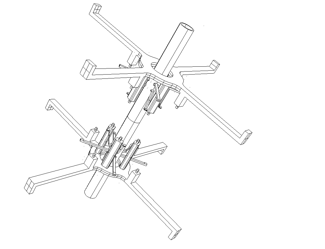
The locking/unlocking mechanisms (LUM) of the test bodies are shown in Fig. 4.1, showing the PGB tube, enclosing the coupling arms and the mechanical suspensions of the test bodies, and the top and bottom LUM. The test bodies are not shown in this Figure to help understanding how locking/unlocking is achieved. Each LUM (there is one at the top and one at the bottom) has: 4 mechanical arms connecting it rigidly to the PGB laboratory, 8 fixing cylindrical bullets, 4 for holding the inner test cylinder and 4 for holding the outer test cylinder, which are inserted into the test bodies during the GG assembling (note that the inner test cylinder has smaller height than the outer one and therefore the bullets for holding it need to be mounted on higher supports); 8 actuators, 4 per test body, to pull out the cylindrical bullets whereby unlocking the test bodies; a transmission mechanism. At the time of unlocking the actuators, by means of the transmission mechanism, pull out the cylindrical bullets from the test bodies whereby freeing them. The actuators taken into consideration for this purpose are either electric motors or paraffin actuators (as used already in BeppoSAX). The electric motors would be located on the mechanical arms far away from the test bodies; in any case, they need to be used only once, at the beginning of the operation phase. After unlocking the motors would be switched off and, in case of paraffin actuators, the required heat would be dissipated and the heat source turned off. Note that, once freed, the test bodies are constrained by mechanical stops which allow them to perform only little movements (about
0.5 cm room). This is well visible in Fig. 4.1, showing the shafts sticking out of the PGB tube (8 per test body, 4 at the top and 4 at the bottom, each arm at 90º from the next). In addition, as discussed in Sec. 2.1.6, Fig. 2.20, a finer locking is available by means of inch-worms equipped with pressure sensors (8 per test body, 4 at the top and 4 at the bottom) which allows fine release and ensures a safe transient from the initial unlocking to the dynamical state at regime simulated numerically in Chap. 6.Item Name |
Material |
Density (g/cm3) |
Mass (kg) |
Quantity |
Internal Test mass |
Copper |
8.96 |
10 |
1 |
External Test Mass |
Beryllium |
1.84 |
10 |
1 |
PGB Case (Cylinder+Covers) |
Aluminum (ERGAL) |
2.8 |
43.647 |
1 |
(Partial Total) |
(63.647) |
|||
Test Body Mechanism (outer mass) |
TiAl6V4 |
4.5 |
0.066 |
2 |
Test Body Mechanism (inner mass) |
TiAl6V4 |
4.5 |
0.048 |
2 |
L.U.M. (top) |
Aluminum (ERGAL) |
2.8 |
1.16 |
1 |
L.U.M. (bottom) |
Aluminum (ERGAL) |
2.8 |
1.16 |
1 |
Active Dampers on Test Bodies |
Aluminum (ERGAL) |
2.8 |
0.019 |
16 |
Active Dampers on PGB |
Aluminum (ERGAL) |
2.8 |
0.019 |
16 |
Active Dampers Arms |
TiAl6V4 |
4.5 |
0.014 |
32 |
Read-out Capacitors, Inch-worms, Rods |
1 |
|||
(Partial Total ) |
(3.486) |
|||
Total Payload Mass |
67.133 |
Table 4.1
Mass budget of the GG payload. The various components of the payload are listed, save for the electronics and the payload computer. This Table is consistent with Table 5.18, giving the GG total mass budget, where mass margins are also taken into account.The locking/unlocking mechanism mounted with the inner test cylinder is shown in Fig. 4.2. The outer test cylinder is shown in Fig. 4.3, with the PGB tube only and no locking/unlocking mechanism. This figure shows clearly the 4 shafts at the top sticking out of the PGB tube, inside which they are connected together and suspended by a spring to the arms that couple the test bodies via flat gimbals, as shown in Fig. 2.1.
The relative position of the test cylinders is sensed by means of 4 capacitance plates, with cylindrical curvature, located in between them at 90º from one another forming 2 capacitance bridges (see Fig. 4.4). Each plate is rigidly connected to the PGB tube via two inch-worms (one at the top and 1 at the bottom) for fine adjusting its position halfway between the outer surface of the inner cylinder and the inner surface of the outer one (mechanical balancing of the bridge). The relative position of each test cylinder with respect to the PGB is sensed also by means of two capacitance bridges, however the plates of the bridges in this case are much smaller (see Fig. 4.2). These small capacitors are used as actuators as well, to damp the relative whirl motions (see Sec. 2.1.5 and Chap. 6), hence, each test body has 8 small dampers, 4 at the top and 4 at the bottom, at 90º from one another. Each damper is made of 2 little plates facing each other; one plate is rigidly connected to one test cylinder and the other to the case of one inch-worm, which in its turn is rigidly connected to the PGB tube. In this way they can sense the relative position of each test body with respect to the PGB and also actuate according to appropriate control laws. Fig. 4.4 shows the dampers (in light blue): in this figure each damper of the inner test cylinder is connected on both ends (one plate to the test cylinder and the other plate to the inch-worm case), while those of the outer test cylinder are connected only to the inch-worm cases because the outer test cylinder is not shown. Although they are not shown in any of these drawings, there are active dampers also between the PGB tube and the spacecraft, as schematized in Fig. 2.7. Each damper is made of two little plates, just like those described here for the test bodies; the inner plate is rigidly connected to the PGB tube while the outer one is rigidly connected to a short spacecraft tube; in addition, axial movements between the PGB and the spacecraft can be sensed and adjusted, which requires 8 additional small dampers between the PGB and the spacecraft, 4 at the top and 4 at the bottom (see Fig. 2.7). In total, the PGB has 16 small dampers.
Figure 4.1 The PGB tube, enclosing the coupling arms and the mechanical suspensions of the cylindrical test bodies (not shown) and their locking/unlocking mechanisms, one at the top and one at the bottom. Every such mechanism shows: 4 mechanical arms (for rigid connection to the PGB cylindrical surface), 8 cylindrical bullets for holding the test cylinders (4 per test cylinder, each cylindrical bullet has its own actuator). The actuators are shown enclosed in a metallic case above or below each cylindrical bullet. Although the test cylinders are not shown, the shafts which stick out of the PGB tube (8 per test body, 4 at the top and 4 at the bottom) are well visible; they are rigidly connected to the test bodies on the far end and to the suspension springs on the other (the suspension springs are located inside the PGB tube as it is better shown in a section through the spin/symmetry axis, as in Fig. 2.1). Only limited movements (about half a cm) are permitted to each shaft, hence to the test bodies; this feature is also referred to as a mechanical stop.
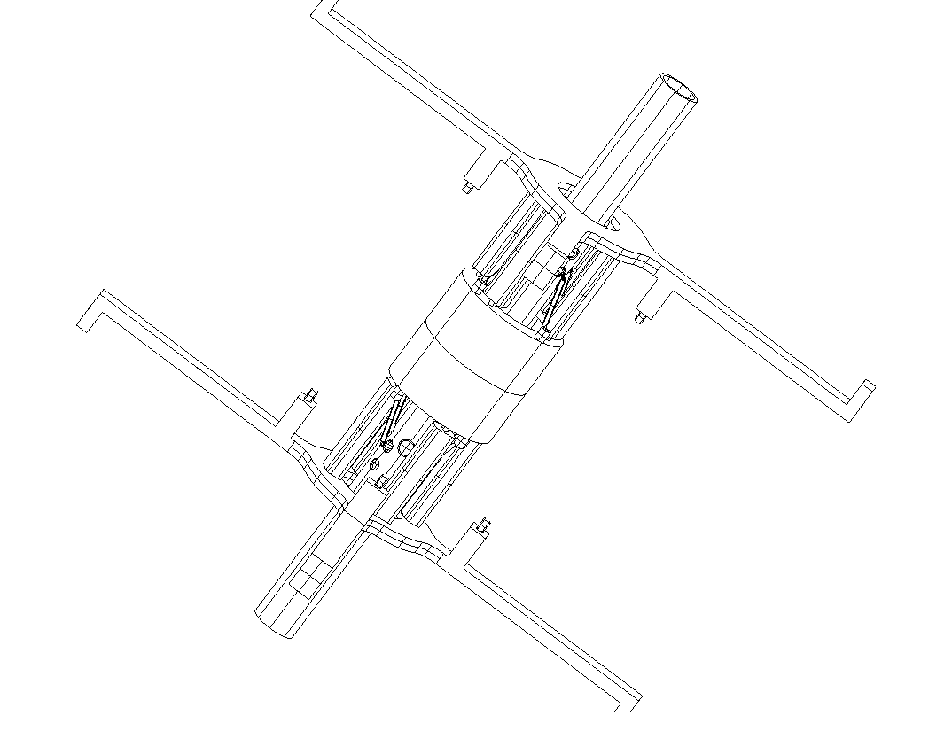
Figure 4.2. The locking/unlocking mechanisms as in Fig. 4.1 with the addition of the inner test cylinder mounted and locked by means of the 8 cylindrical bullets (4 at the top and 4 at the bottom) of the locking/unlocking device previously shown in Fig. 4.1
A 3-D view of the PGB tube, the locking/unlocking mechanisms, the inner test body, the read-out capacitors, the inch-worms and the small plates of the capacitance sensors/actuators is shown in Fig. 4.4. The outer test cylinder is not drawn in this figure since it would prevent all parts inside it from being seen; the inch-worms are schematized as small cylinders in light-blue, the small plates of the capacitance sensors/actuators are shown in light blue; the large capacitance plates of the read-out are shown in pink; the locking/unlocking mechanisms are well visible in gray. The caption of Fig. 4.4 gives a rather detailed description of the GG experimental apparatus inside the PGB laboratory with the help of colors. It is worth adding that power and signals are brought inside the PGB via its helical suspension springs (3 wires each spring), as described in Chap. 2.1 (see Sec.2.1.1 and Fig. 2.5). No electric signal goes through the helical springs which suspend the test bodies (2 for each body, not shown in any of these figures because they are located inside the PGB tube; see Fig. 2.1). The piezoceramics used for calibration and for adjusting the arms which couple the test cylinders (also located inside the PGB tube and therefore not shown) need to be commanded: this requires 3 wires, which are selected to be 3 of the 6 wire sectors of each of the two flat gimbals through which the coupling arms are connected to the PGB tube, so that they can be insulated at their clamping rings (see Sec. 2.1.1 and Fig. 2.3).
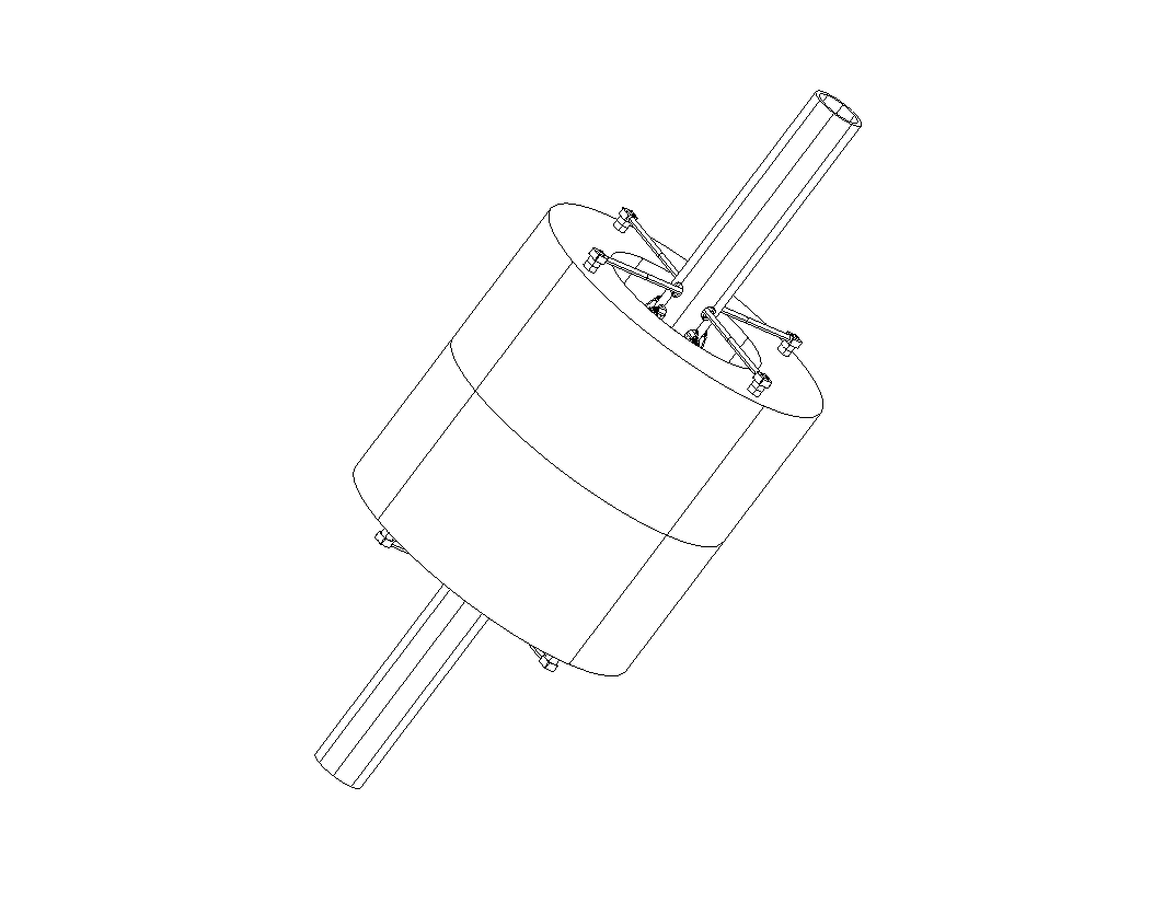
Figure 4.3 The PGB tube and the outer test cylinder. The locking/unlocking mechanism is not shown. The read-out capacitors and inner test mass are hidden by the outer test cylinder. The 4 shafts (at the top) which stick out of the PGB tube and are connected to the outer cylinder are clearly visible (there are 4 shafts at the bottom as well). It is apparent that the body is permitted very limited movements only (by about half a cm) because the 4 shafts are constrained by mechanical stops consisting of small holes on the PGB tube (usually referred to as mechanical stops). All 4 of them connect together inside the tube, where a suspension helical spring connects them (hence the test body) to one coupling arm located inside the tube. Another helical spring connects the 4 shafts located at the bottom to the other coupling arm inside the PGB (see Fig. 2.1 for a section through the spin/symmetry axis).
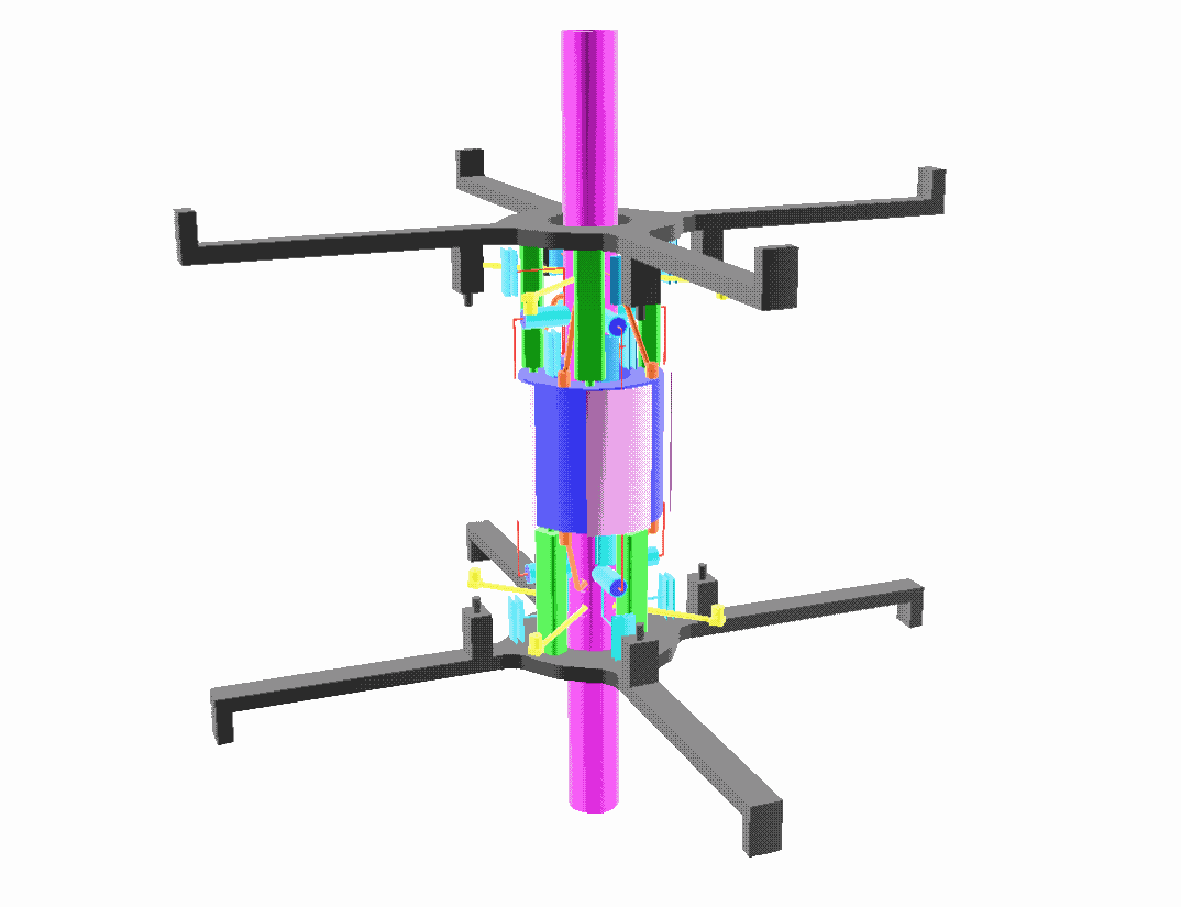
Figure 4.4 Overall, 3-D view of the GG experimental apparatus internal to the PGB laboratory (only the central tube of the PGB is shown (in dark pink). Of the actual apparatus that will be located inside the PGB everything is shown here except the outer test cylinder, which would hide all the components inside it. The locking/unlocking mechanisms are shown in gray; the cylindrical bullets and their actuators, also in gray, are well visible only for the outer test cylinder; the inner test cylinder is locked. It is shown in blue, partially covered by the capacitance plates of the read-out (in pink). The inch-worms for the mechanical balancing of the plates are schematized as small cylinders in light blue. Note that these plates are rigidly connected (through the inch worms) to the PGB tube. There is one inch-worm per radial shaft, each plate has 2 shafts, 1 at the top and 1 at the bottom, amounting to 8 shafts and 8 inch-worms for the total read-out system. The small plates of the active dampers are shown in light blue. Each damper consists of 2 halves: 1 is connected to the inch-worm case, hence to the PGB, and the other to the test body. In this way it is possible to sense the relative position of each test body with respect to the PGB, and to actuate in order to damp their whirl motions (see Chap. 6)
![]()