
4.2 FEEP Thrusters and Control electronics
The FEEP Thruster Concept Field Emission Electric Propulsion (FEEP) is an electrostatic propulsion concept (Bartoli et al., 1984) based on field ionization of a liquid metal and subsequent acceleration of the ions by a strong electric field. FEEP is currently the object of great interest in the scientific community, due to its unique features: 1 µN to 1 mN thrust range, near instantaneous switch on / switch off capability, and high-resolution throttleability (better than one part in 104), which enables accurate thrust modulation in both continuous and pulsed modes. Presently baselined for several scientific missions onboard drag-free satellites, this propulsion system has been also proposed for attitude control and orbit maintenance on commercial small satellites and constellations (Marcuccio et al., 1997). Developed at Centrospazio with power and control electronics made by Laben, the FEEP system will be flight tested on a Get Away Special canister onboard the Space Shuttle in early 2000.
In the past, most FEEP development efforts were focused on enhancing the current extracted, in an attempt to obtain higher thrust levels. At thrust levels of above a few milli-Newton, FEEP has some drawbacks due to the very high specific impulse, which is associated with a very high power-to-thrust ratio. As no established solution was identified to reduce specific impulse, the development of FEEP as a milli-Newton level thruster was almost terminated in the late ‘80s. The recent shift of perspective on FEEP technology, which now focuses on the very low current capability of this thruster, has drastically changed this situation. At very low thrust levels (i.e., in the micronewton range), the traditional FEEP slit emitter performs best, and its features make it the only candidate for several space applications.
In FEEP emitters, unlike most ion engines, ions are directly extracted from the liquid phase. The thruster can accelerate a large number of different liquid metals or alloys. Cesium is usually selected for its high atomic weight, low ionization potential, low melting point (
28.4 °C), and good wetting capabilities on the emitter substrate. Specific impulse is in the 4000 - 10000 s range, and may be easily adjusted to meet specific mission requirements. Thrust level can be finely tuned (Marcuccio et al., 1998), and instantaneous switching capability allows pulsed mode operation and accurate thrust modulation at high bandwidth.Thrust is produced by exhausting a beam of mainly singly-ionized Cesium atoms, produced by field evaporation. The emitter module consists of two metallic plates with a small propellant reservoir. A sharp blade is accurately machined on one side of each plate. A thin layer of
Ni is sputter-deposited on the other three sides of one of the plates, to act as a spacer; when the two emitter halves are tightly clamped together, a slit of about 1 µm is left between the blades. Cesium flows through this tiny channel, forming a free surface at the exit of the slit with a radius of curvature in the order of 1 µm. Under a strong electric field generated by the application of a voltage difference between the emitter and an accelerator electrode located directly in front of it, the free surface of the liquid metal approaches a condition of local instability, due to the combined effects of the electrostatic force and the surface tension. A series of protruding cusps, or "Taylor cones," are created. When the electric field reaches a value of about 109 V/m, the atoms at the tip spontaneously ionize and an ion jet is extracted by the electric field, while the electrons are rejected in the bulk of the liquid. An external source of electrons provides negative charges to maintain global electrical neutrality of the thruster assembly. Mass flow rate is extremely low and requires no control, as the particles extracted are replaced by the capillary actions from the propellant reservoir at a rate sufficient to maintain dynamic equilibrium at the emitter tip. When voltage is removed, the capillary force prevents the propellant from pouring out of the slit.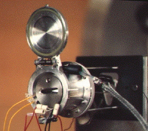
Thruster Development Status A FEEP thruster endurance test, aimed at totaling
2000 hours of operation, is under preparation in the ESTEC Electric Propulsion Laboratory under the responsibility of Centrospazio. Starting in end 1998, this test will exploit a set of diagnostics (ion beam probes, quartz crystal microbalances, etc.) to fully characterize the thruster performance and the plume effects on nearby surfaces.Realization of a thrust balance (Paolucci
et al., 1997) is underway. The envisaged design is aimed at measuring 100 µN maximum thrust with a resolution of 0.1 µN.The thruster design is being finalized for its first space test. In 1997, ESA awarded a contract to Centrospazio to perform a FEEP flight demonstration (Marcuccio
et al., 1998) on a Get Away Special (GAS) canister onboard the Space Shuttle. The industrial team set up to carry out this task includes Centrospazio as prime contractor, with LABEN (Milan, Italy) and Techno System Developments (Pozzuoli, Italy) as subcontractors for the FEEP Electronics Unit (FEU) and the GAS Experiment Electronics, respectively. Known as EMITS (Electric MIcrothruster Test in Space), this experiment is aimed at:• demonstrating that the FEEP system is robust enough to withstand typical launch loads;
• firing the thruster in space for the first time;
• demonstrating the propellant storage and container sealing functionality;
• demonstrating proper operation in microgravity of propellant feeding by capillarity;
• demonstrating thruster proper operation in such an adverse environment as the low altitude, water vapor- and oxygen-rich Shuttle orbit;
• demonstrating ion beam neutralization;
• assessing the plume current distribution;
• evaluating the propellant backflow and deposition on surrounding surfaces;
• testing the power conditioning unit in operational environment.
Direct thrust measurement will not be performed, to avoid excessive complication of the experimental setup. Indirect thrust measurement will be performed using the electrical parameter data. Evidence of the ion beam presence will be gained by means of electrical measurements in the thruster’s power supply lines and, independently, by means of ion beam electrostatic probes.
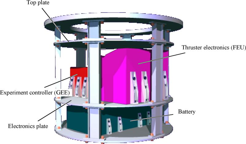
The experiment will be accommodated in a GAS canister, equipped with a Motorized Door Assembly (MDA). The GAS/MDA hardware and the flight onboard the Shuttle are provided by NASA, through an existing agreement with ESA. The GAS canister doesn’t receive power, nor exchanges data with the Shuttle, except a pre-defined set of four telecommands used to switch on and off the experiment. Therefore, all the necessary experiment hardware and support equipment must be carried within the GAS, including:
• the battery pack;
• the experiment management electronics, including raw power conditioning,
onboard computer, data acquisition and storage;
• the thruster power electronics;
• the thrusters, including the neutralizers;
• the movable electrostatic probe assemblies and the propellant deposition monitors.
The experiment layout is shown in Fig. 4.7.
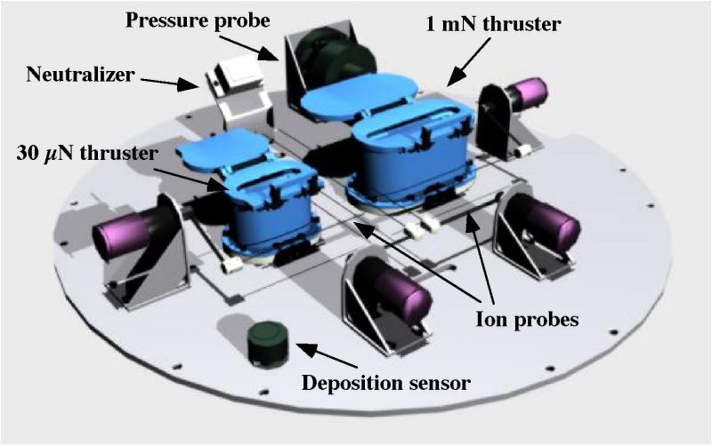
EMITS will feature two different thruster assemblies, each including its own sealed container, heater, temperature sensor, emitter and accelerator. In order to cover the thrust ranges of interest of both commercial and scientific applications of FEEP, the following two emitter slit lengths have been selected:
•
2 mm slit length: nominal thrust = 30 µN, power consumption = 1.8 W;•
70 mm slit length: nominal thrust = 1 mN, power consumption = 60 W.The thruster module design includes a sealed container, to protect the thruster during the pre-launch phases. The container provides a sealed envelope filled with an inert gas, which protects the emitter from interaction with air, to avoid slit clogging due to formation of propellant oxides from the moment of propellant filling to thruster operation start in orbit. A new container assembly has been recently developed to host the
30 µN, 2 mm slit length emitter. The new container features an improved sealing system and a paraffin actuator for lid release.The liquid metal used as propellant (
Cs or Rb) will be stored in the emitter internal reservoir. Propellant feeding to the emitter tips will be performed by capillarity. The emitters will be loaded with about 2 grams of propellant each. The onboard controller will record, at appropriate sampling rates, the main electrical parameters (thruster voltages and currents), several temperatures (emitters, neutralizers, FEU, onboard computer, battery) and the data from the propellant deposition sensors. All data will be stored onboard, and will be available for analysis upon Shuttle return from orbit.As of October, 1998, NASA has approved the EMITS Payload Accommodation Requirements and EMITS has been assigned payload number G-752.
More information can be found on the Internet at http://www.centrospazio.cpr.it
4.2.2. FEEP Control Electronics
The FEEP Electronic Unit proposed for GG is being developed in Laben under an ESA contract. The Block Diagram of this unit is shown in Fig. 4.8. The unit can be easily adapted to the GG needs; two units are needed to manage the 8 FEEP thrusters currently foreseen for GG. The FEEP Electronic Unit is constituted by the following items:
Figure 4.8 Block diagram of the FEEP Electronic Unit
Emitter HVPS. The Emitter HVPS provides a positive high voltage programmable in the range
3KV to 5KV. Current specifications are:Input voltage range
24 to 28 V (TBC)Output voltage range
3KV (min), 5KV (max.)Output voltage stability <
1.5VHV max. ripple Less than
1.5VHV load min load: no load
max. load:
300 AProgrammability Digital commands.
Output protection Over current protection <
2mADynamic performance The output voltage shall vary from
3KV to 5.5KV, sinus wave 2Hz., i.e. the converter bandwidth shall be at least 20Hz The required dynamic performances can cause an additional power dissipation. In fact the low output ripple requires filter capacitance. This capacitance shall be charged and discharged at 2Hz. The additional needed output current is given by:I= CdV/dTmax = 2 fCA
For
C=10 nF, A=1.5 KV, f=5Hz I=300 AAdditional power dissipation:
P= fC(V12 +V22)
for
C=10 nF, f=2Hz, V1 = 5KV, , V2 = 2KV P=0.4 WAccelerator HVPS . The Accelerator HVPS provides a negative high voltage programmable in the range
3KV to 5.5KV. The current specifications are:Input voltage range
24 to 28 V (TBC)Output voltage range -
3KV (min), -5.5KV (max.)Output voltage stability <
1.5VHV max. ripple Less than
1.5VHV load min load: no load
max. load:
100 AProgrammability Digital commands.
Output protection Over current protection <
1mADuring flight operations the Accelerator voltage will be set at a constant value and propulsor thrust controlled by means of the emitter voltage, being the ions emission related to the total voltage difference between the two. For the above reason only one Accelerator HVPS can be used for a cluster of 4 thrusters, and then all the thruster accelerator will be permanently connected to the positive voltage which will be maintained ON during the mission. This solution will save mass and volume with a small drawback of a permanent power consumption estimated in about
0.5W.Control Electronics. The Control Electronics provides the interfaces to the Payload Data Processor and control the main thruster parameters such as:
Proposed Solution. The overall propulsion system for GG foresees 8 thrusters, in two clusters. Each cluster is powered and driven by an electronic unit FEU (FEEP Electronic Unit). The Emitter and Accelerator HV Power Supply will be based on the well known and tested Topology constituted by a Flyback converter followed by a Cockcroft-Walton multiplier. Due to the great accuracy required on the output voltage, feedback shall be taken directly to the output, moreover matched resistor HV divider, precision operational amplifiers, stable voltage reference are needed to insure the requirement. The Power Supply HV parts shall be completely encapsulated and shielded to prevent EMI problem which are critical for the experiment. A block diagram of the Emitter power supply is given in Fig. 4.9. The power needed by the neutralizer will be provided directly by the main DC-DC converter which provides power to the control circuitry
Fig. 4.9 Emitter High Voltage Power Supply
Control System. The control system is in charge of:
The control system will be based on a general purpose RISC micro controller design
Budget. A preliminary estimate of the mass, dimensions and power consumption is given hereafter. Mass and dimension estimates are based on the assumption that 8 thrusters, and therefore two electronic units, are needed. Each unit will house four Emitter HV supplies, one Accelerator HVPS, Neutralizer and control and monitor electronics
. The mass of each unit is 5.5 kg (hence 11 kg total) and the dimensions are: 250x140x200 mm (each unit)The power budget is strongly dependent on the number of thrusters which are activated at the same time and on the required power to heat the neutralizer and the emitter. A preliminary estimate is
30 W for each unit assuming that 2 thrusters are activated simultaneously at the minimum thrust.